


25
pliers from side to side, so as not to bend chip pins. Pull loosened
EPROM all the way out.
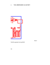
4. Install the new EPROM into socket U2. The EPROM is notched; the
notch on the EPROM should line up with the notch on the socket. Be
careful not to bend any of the pins. Make sure none of the pins miss
their sockets. If the socket has more holes than chip pins, the pins
should line up starting at the edge of the board.
5. Re-install the V93A and apply power to the unit. The upgrade is now
complete. Before you begin operations, check the configuration status
to make certain it matches your application. See Section 5 for
complete instructions.