


D8125INV
Overview
D8125INV Operation and Installation Guide
49690E Page 10 © 2005 Bosch Security Systems
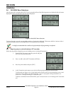
• All RF points will initialize in a normal state when power is reapplied
• Alarms initiated prior to power loss would be reset. If the alarm conditions persist when power is restored,
new alarms would be generated.
Note: Programmed settings such as RF point configuration and System ID will remain intact upon the event of a power
loss.
2.2.2 System Supervision
2.2.2.1 Watchdog
The D8125INV implements a watchdog software. Failure of the program will result in a software reset within two
seconds. This may cause a trouble condition on the control panel for the duration of the reset.
2.2.2.2 Self-Testing
The D8125INV EEPROM memory is automatically tested on a periodic basis. The EEPROM checksum is verified every
ten minutes. If the EEPROM checksum fails, a point bus trouble condition will be seen at the control panel.
2.3 D8125INV Inovonics Interface Module Point Expansion Description
Using two D8125INVs, you can program up to 238 (119 per bus) Inovonics Wireless Transmitters to the system on the
D9412GV2, D7412GV2, D9412G, D7412G, D9412, D7412, D7212, and D9112 allow up to 67 Inovonics Wireless
Transmitters, and D7212GV2 and D7212G allow up to 32 Invonics wireless transmitters.
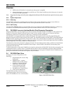
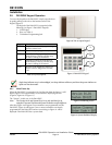
The D8125INV is an integrated interface module and keypad. The keypad is used to access the programming, and
diagnostic functions of the wireless portion of the system. The integrated keypad on the D8125INV is physically different
looking from the typical keypads (D1255, D1256, D1257, and so on) so that it will not be mistaken for a system keypad.
When mounting the D8125INV, it must be within 5 feet (of the control panel. It has been designed such that it should be
mounted right next to the D8103, D8108A or D8109 enclosure.
The D9412GV2, D7412GV2, D7212GV2, D9412G, D7412G, D7212G, D9412, D7412, D7212, and D9112 Control Panels
can have both hardwired (D8128D OctoPOPITS, D8125 Popex / D9127 POPITS, D8125MUX) and wireless points
connected at the same time.
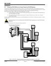
To add wireless points, an Inovonics FA400 Receiver must be connected to the D8125INV which is then connected to the
control panel’s Zonex 1 (and/or Zonex 2) terminals and Aux Power. For best transmitter reception results, the FA400
should be centrally located among the transmitters. If transmitters are at too great of a distance for the FA400 Receiver to
pick up the transmission, an Inovonics RF Repeater may be installed.
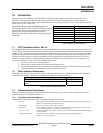
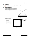
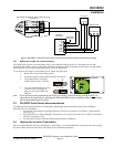
2.4 D8125INV Back View
See Figure 1 for areas of importance on the
D8125INV,
1. Programming Jack (Access using
front panel)
2. EPROM Socket – contains
EPROM with encoded software
3. Sounder to indicate valid and
invalid entry via the keypad
4. 4-Wire Zonex Power Panel
Connection Terminal Strip
5. FA-400 Receiver Terminal Strip
6. LCD Contrast Adjustment
The D8125INV provides connection to a
control panel using a Zonex 4-wire interface
and to a FA-400 Receiver via a 3-wire interface.
Figure 1: D8125INV Back View