


D8125INV
Installation
D8125INV Operation and Installation Guide
49690E Page 20 © 2005 Bosch Security Systems
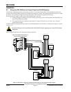
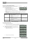
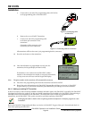
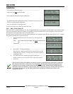
a. Connect the 4-pin end of the programming cable (P/N 50576)
to the programming jack on the D8125INV.
Figure 16: Connecting cable
to D8125INV
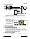
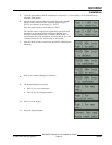
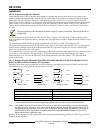
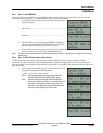
b. Remove the cover of the RF Transmitter.
c. Connect one end of the programming cable
to the three-pin connector on the
transmitter.
Orientation of the connector to the
transmitter pins is not important.
Figure 17: Connecting cable to transmitter
All transmitters will have the same 3-pin programming header (connector)
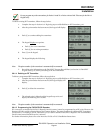
12.
Press the reset button on the transmitter.
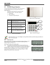
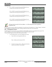
13.
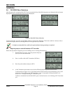
Once the information is programmed correctly into the
transmitter, the keypad display will show briefly.
If transmitter is not connected to the D8125INV within 5
minutes or the transmitter was unable to accept the information,
a 3-beep error tone will occur and the keypad will display:
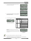
Note: The point number of the transmitter will automatically increment.
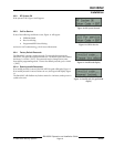
14.
Disconnect the programming cable from the transmitter and the D8125INV.
15.
Record the point information on the D8125INV Program Record Sheet (see Section 5.0 D8125INV
Program Sheet, p.35) and on the transmitter point label before proceeding to the next transmitter.
3.6.1.3 Adding an existing RF Transmitter
It may be necessary to take an already installed transmitter and add it again to the D8125INV (especially if the D8125INV
is damaged and needs to be replaced). In this case, the RF transmitters can be added to the D8125INV without having to
manually connect each transmitter to the D8125INV. The Mode and Check-in time are programmed into the
transmitters, not the D8125INV. This option can only be used when replacing a D8125INV.
If changing the mode or check in time or replacing another manufacturer’s interface, program as a new
transmitter.
Refer to the D8125INV Program Record Sheet (see Section 5.0 D8125INV Program Sheet, p.35) for mode and check-in
time when replacing the D8125INV.