


D8125INV
Troubleshooting
D8125INV Operation and Installation Guide
© 2005 Bosch Security Systems Page 29 49690E
4.0 Troubleshooting
Symptom Diagnosis Remedy
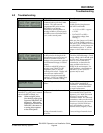
D8125INV has lost
communications with the FA400
receiver. This will cause all
programmed RF points on that
D8125INV to go missing
immediately (missing alarms or
missing troubles at control panel.)
It will also cause a Point Bus Fail 1
(or 2) at the control panel.
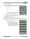
Check for LED activity at
receiver(s).
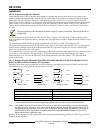
Double-check wiring between
D8125INV and FA400.
• +12 V/Vs to GND = approx.
13 VDC
• DATA/OUT to GND =
fluctuating voltage (data
flowing)
Make sure that jumper on FA400 is
set to '1' if one FA400 is used on a
D8125INV; If two FA400's are used
on a D8125INV, set the jumper on
one FA400 receiver to '1', and the
jumper on the FA400 receiver to
'2'.
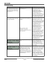
The D8125INV hasn't 'heard' from
an RF point for the length of the
programmed supervision interval.
The most common reasons are
damage to the transmitter, physical
environmental changes, or a dead
battery.
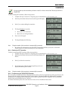
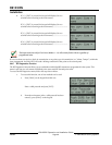
To find out which RF points are
missing, press [DIAG] for RF
diagnostics, then [2] for Off-
normal point’s status. Display will
start at lowest numbered off-
normal point and automatically
scroll up. [NEXT] or [PREV] keys
will switch to manual scrolling.
Locate missing transmitter.
Check for physical damage. Check
battery voltage, which should equal
3.0 VDC min. Bring transmitter
closer to receiver and cause a
transmission, to determine if a
range problem exists due to a
change in the environment. For
range problems, a 2nd FA400 per
D8125INV, or an FA570/575
repeater may be used.
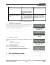
Internal diagnostics checksum
failure
Clear EEPROM, and reprogram
the D8125INV and all of its
transmitters. If EEPROM failure
re-occurs, return the D8125INV
for repair/replacement.
Undesired point response at
D8125INV (e.g. RF point is normal
when it should be faulted, etc.)
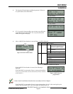
Note: When testing RF points,
first check for proper point
response at D8125INV RF
diagnostics. When point
responses are correct at the
D8125INV, then move on
to testing point responses
at the control panel.
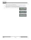
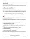
Programmed mode of transmitter
is incorrect.
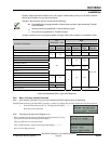
Check the mode charts in Table 9:
Recommended Point Types/Point
Responses, p.23. Make sure mode
selection is correct for that
transmitter model. For Universal
transmitters, make sure the mode
selection is correct for the external
circuit type (NO/NC/EOL?/not
used), and whether or not the
internal contact (magnet) is used.
Wiring of external circuit is
incorrect.
Correct wiring of external circuit