


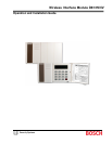

D8125INV
Overview
D8125INV Operation and Installation Guide
© 2005 Bosch Security Systems Page 9 49690E
2.0 D8125INV Overview
2.1 Features
• Compatible with Bosch Security Systems D9412GV2, D7412GV2, D7212GV2, D9412G, D7412G, D7212G,
D9412, D7412, D7212, and D9112 Control Panels. (FA113 can not be used on the D7212GV2 andD7212G
panels)
• Menu driven User Interface
• On the D9412GV2, D9412G, D9412, and D9112, the D8125INV supports up to 2 Inovonics FA400
Receivers (with a maximum of 238 transmitters [119 per bus])
• On the D7412GV2, D7412G, and D7412, the D8125INV supports up to 2 Invonics FA400 Receivers (with a
maximum of 67 transmitters)
• On the D7212GV2 and D7212G, the D8125INV supports up to 2 Invonics FA400 Receivers (with up to 32
transmitters in the same location).
• An unlimited number of FA113 Wireless Keyfobs can be added
• Used for diagnostic functions to troubleshoot system RF Transmitters
• Programmable system-wide supervision time interval and individual transmitter check-in time
• Programmable transmitter configuration (Normally Open/Normally Closed, Internal/External Contact,
EOL Resistor)
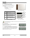
2.2 Specifications
LCD Display 2 lines by 16 characters, Backlit
User Interface:
Keypad 0 – 9 numbers
ESC, ENT, PREV, NEXT and DIAG keys
Operating Voltage:
10.2 - 14 VDC supplied by Aux Power from Control Panel or an External
Auxiliary Power Supply.
Current:
30 mA typical, 45 mA maximum
plus ≈ 40 mA for each FA400 receiver
Operating Temperature:
+32°F to +149°F (0°C to +65°C), 93% Relative Humidity
Wiring:
18 AWG or 22 AWG Solid or Stranded. Maximum distance from control
panel cannot exceed 5 ft. (1.5 m).
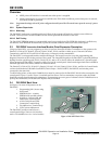
Dimensions (HxWxD):
3.94 in. x 6.5 in. x 1.2 in. (10 cm x 16.6 cm x 3 cm)
Weight:
8.6 oz. (243 g)
Table 3: D8125INV Specifications
Operating Voltage:
10.2 VDC to 14 VDC
Curent:
40 mA Max.
Wiring:
18 AWG or 22 AWG Solid or Stranded. Maximum distance from D8125INV
to FA400 cannot exceed 200 ft. (61 m) or 1000 ft. (305 m) with power supply.
Table 4: FA400 Specifications
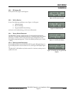
2.2.1 Power
If the D8125INV is powered down and then back up, it may take up to a maximum of 5 minutes (up to 15
minutes for 5 minute Transmitter Check-In Time) for all the transmitters to report back to the D8125INV
with their current status. On systems employing fewer transmitters, this time is reduced proportionately.
In addition, when the D8125INV is powered up, all programmed RF points will report Normal until their
state is updated.
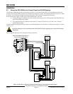
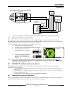
The D8125INV power should be connected to the control panel using the Aux Power terminals. If the D8125INV were to
lose power, the following conditions may result:
• All RF points will report to the control panel as missing (trouble/alarm)