


D8125INV
Contents
D8125INV Operation and Installation Guide
49690E Page 4 © 2005 Bosch Security Systems
4.3 Low Transmitter Battery Conditions.............................................................................................................................31
4.4 D8125INV Power Cycle Operation..............................................................................................................................32
4.5 Inovonics Frequently Asked Questions .......................................................................................................................32
4.5.1 What's the range of Inovonics Wireless transmitters? ............................................................................................32
4.5.2 What is the range of the Inovonics Wireless repeater? ..........................................................................................32
4.5.3 What does the red decode LED/ light mean?...........................................................................................................32
4.5.4 Does it matter what way I plug in the programming cable?....................................................................................32
4.5.5 How can I get more range?............................................................................................................................................32
4.5.6 Why can't I program more than 1 transmitter per point? ........................................................................................32
4.5.7 Are your transmitters weatherproof?............................................................................................................................32
4.5.8 What is temperature range for good operation?.......................................................................................................33
4.5.9 Can I externalize an antenna?........................................................................................................................................33
4.5.10 Does each transmitter need a repeater?.....................................................................................................................33
5.0 D8125INV Program Sheet ..........................................................................................................................................................35
Figures
Table 1: Update Kit Part Numbers ..............................................................................................................................................7
Table 2: Other Literature Referenced ..........................................................................................................................................7
Table 3: D8125INV Specifications...............................................................................................................................................9
Table 4: FA400 Specifications ......................................................................................................................................................9
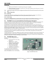
Figure 1: D8125INV Back View.................................................................................................................................................10
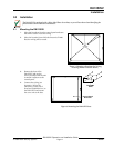
Figure 2: Choosing a Knockout for Wiring Routing (D8103 enclosure shown) ....................................................................11
Figure 3: Mounting the D8125INV base...................................................................................................................................11
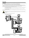
Figure 4: D8125INV to D9412GV2/D9412G/D9412/D9112 Control Panel Wiring Diagram...............................................12
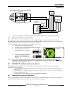
Figure 5: D8125INV to D7412GV2/D7212GV2/7412G/D7212G/D7412/D7212 Control Panel Wiring ..............................13
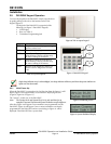
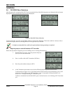
Figure 6: Tab to expose keypad..................................................................................................................................................14
Figure 7: D8125INV Keypad......................................................................................................................................................14
Table 5: Key Descriptions...........................................................................................................................................................14
Figure 8: Initializing screen........................................................................................................................................................14
Figure 9: System Defaulted Display...........................................................................................................................................14
Figure 10: RF System Normal....................................................................................................................................................15
Figure 11: Call for Service ..........................................................................................................................................................15
Figure 12: Invalid code display ..................................................................................................................................................15
Figure 13: Invalid code, Keypad locked display........................................................................................................................15
Figure 14: D8125INV Menu Selections.....................................................................................................................................16
Table 6: Recommended Mode Values.......................................................................................................................................17
Figure 15: RF Transmitter status ...............................................................................................................................................18
Figure 16: Connecting cable to D8125INV...............................................................................................................................20
Figure 17: Connecting cable to transmitter...............................................................................................................................20
Figure 18: Point Number Status ................................................................................................................................................27
Figure 19: RF Point not programmed .......................................................................................................................................27
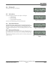
Figure 20: Call for Service, Enter Code + ENT ........................................................................................................................31
Figure 21: Call for Service, Receiver Missing ............................................................................................................................31
Figure 22: Call for Service, Enter Code + ENT ........................................................................................................................31
Figure 23: Call for Service, Receiver Missing ............................................................................................................................31