


D8125INV
Introduction
D8125INV Operation and Installation Guide
© 2005 Bosch Security Systems Page 7 49690E
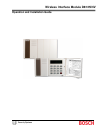
1.0 Int roduction
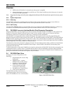
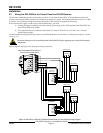
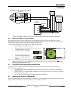
This guide covers the installation of the D8125INV Wireless Interface Module for Inovonics Transmitters. The
D8125INV is an interface module that allows the connection of an Inovonics FA400 Receiver and compatible
transmitters. The D8125INV may be used with the following control panels: D9412G, D7412G, D9412GV2, D7412GV2,
D9412, D9112, D7412, and D7212.
Control Panel Update Kit Part Number
D9412G, D9412 D9499-0650 or higher
D9112 D9199-0650 or higher
D7412G, D7412 D7499-0650 or higher
D7212 D7299-0650 or higher
D9412GV2 All Revs
D7412GV2 All Revs
D7212GV2 All Revs
Control Panel Firmware Revision Requirements: The
control panels listed in Table 1 must have firmware version
6.30 or higher. If you need to upgrade the control panel
firmware of a currently installed system, order the
following Update Kits from Bosch Security Systems Order
Processing:
Table 1: Update Kit Part Numbers
1.1 FCC Compliance Notice, Part 15
This equipment has been tested and found to comply with the limits for a Class B digital device, pursuant to Part 15 of
the FCC Rules. These limits are designed to provide reasonable protection against harmful interference in a commercial
installation. This equipment generates, uses, and can radiate radio frequency energy, and, if not installed in accordance
with the instructions, may cause harmful interference to radio communications. However, there is no guarantee that
interference will not occur in a particular installation. If this equipment does cause harmful interference to radio or
television reception, which can be determined by turning the equipment on and off, the user is encouraged to try to
correct the interference by one or more of the following measures:
1. Reorient or relocate the receiving antenna.
2. Increase the separation between the equipment and the receiver.
3. Connect the equipment into an outlet on a circuit different from that to which the receiver is connected.
4. Consult the dealer or an experienced radio/TV technician for help.
1.2 Other Literature Referenced
Throughout this manual, references will be made to other documentation. See the following table for the documents
referenced in this manual, which lists the complete part number for ordering purposes.
Name of document Part Number
D9412G/D7412G/D9412GV2/D7412GV2 Program Entry Guide 47775
D9412G/D7412G/D9412GV2/D7412GV2 Operation and Installation
Manual
43488
Table 2: Other Literature Referenced
1.3 Documentation Conventions
These conventions are intended to call out important features, items, notes, cautions, and warnings that the reader
should be aware of in reading this document.
1.3.1 Type Styles Used in this Manual
To help identify important items in the text, the following type styles are used:
Bold text Usually indicates selections that you may use while programming your control panel. It may also
indicate an important fact that should be noted.
Bold Italicized used to denote notes, cautions and/or warnings
Italicized text Is used to reference the user to another part of this manual or another manual entirely. It is also
used to symbolize names for records that the user will create.
Courier Text
Text that appears like this indicates what may appear on the D5200 Programmer display, keypad,
or internal printer.
[CAPITALIZED TEXT] Text like this is used to indicate to the user that a specific key should be pressed.
Example: …press the [ESC] key…