


D8125INV
Installation
D8125INV Operation and Installation Guide
49690E Page 14 © 2005 Bosch Security Systems
3.5 D8125INV Keypad Operation
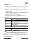
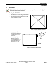
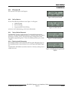
To access the keypad on the D8125INV, simply open the door
by gently pulling on the tab on the bottom center of the
keypad (Figure 6).
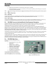
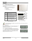
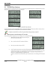
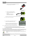
The keypad of the D8125INV is comprised of the
following (see Figure 7: D8125INV Keypad):
1. LCD Display
2. Keys (see Table 5)
3. Transmitter Programming Jack
Figure 6: Tab to expose keypad
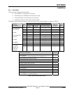
Key Description
ESC Escape – Backs out of a programming
option or menu level.
ENT Enter – Accepts a program entry.
PREV Manually scrolls to a previous menu or
point selection. This key will also stop
the auto-scrolling of the menus.
NEXT Manually scrolls to the next menu or
point selection. This key will also stop
the auto-scrolling of the menus.
DIAG Shortcut to RF Diagnostics menu (see
Section 3.6.6 RF Diagnostics Function,
p.26)
Table 5: Key Descriptions
3
1
2
Figure 7: D8125INV Keypad
Single beep indicates entry is acknowledged, two beeps indicate valid entry and three beep tones indicate an
input error has been made.
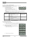
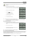
3.5.1 Initial Power-Up
When the D8125INV is powered up for the first time from the factory, it will
display Figure 8 for approximately 3 seconds before displaying idle text
(Figure 9, Figure 10 or Figure 11).
The “System”, in this case, is the D8125INV.
Note: The Version 01.01 and System ID of 123 is only used here for an
example. The actual Version and System ID number may be different.
Figure 8: Initializing screen
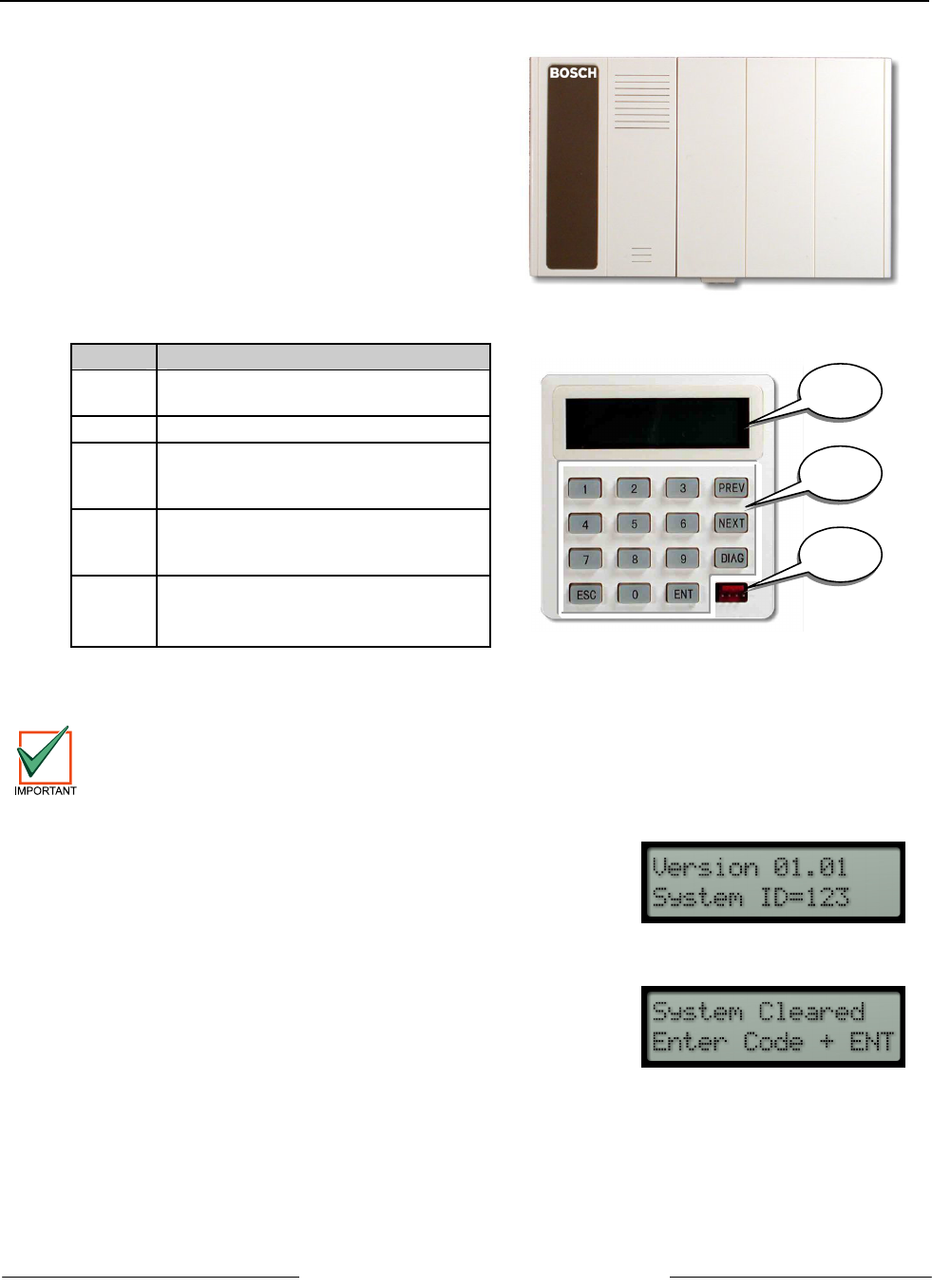
After that, Figure 9 will appear if no transmitters are programmed into the
D8125INV, Figure 10 will appear if one or more transmitters are already
programmed in the D8125INV and are not missing, or Figure 11 will be
displayed if the D8125INV has a system fault.
Figure 9: System Defaulted Display