2E43-51/2E43-51R User’s Guide 4-1
CHAPTER 4
TROUBLESHOOTING
This chapter provides information concerning the following:
• Using the LANVIEW diagnostic and status monitoring system
• Troubleshooting network and 2E43-51 operational problems
• Using the RESET button
4.1 USING LANVIEW
The 2E43-51 uses Cabletron Systems built-in visual diagnostic and status
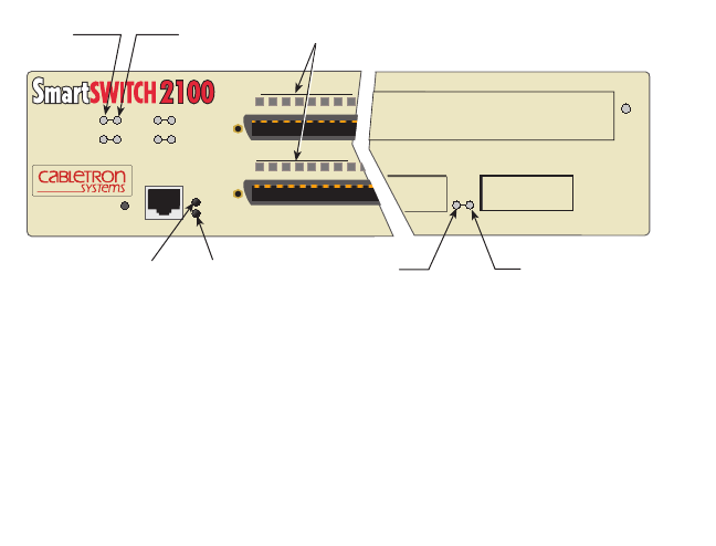
monitoring system called LANVIEW. The LANVIEW LEDs (Figure 4-1)
allow quick observation of the network status to aid in diagnosing
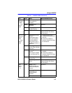
network problems. Refer to Table 4-1 for a description of the LEDs.
For a functional description of the LANVIEW LED on the optional Fast
Ethernet Interface Module (FE-100TX), refer to Section 4.2.
All LEDs for the High Speed Interface Module (HSIM) are located on the
HSIM and are described in the associated HSIM user’s guide.
Figure 4-1 LANVIEW LEDs
12
12
LINK 1
LINK 1
ENET 1
ENET 3
E3
E1
E4
E2
ENET
FE Module
RX TX
2E43-51
COM
PWR
CPU
RESET
2251-36
TXRX
CPU
PWR
LINK
HSIM-ASDP
6


