


2-6 SmartSwitch 9A100 User Guide
Configuring the Switch Switch Installation and Setup
2.4 CONFIGURING THE SWITCH
Initial configuration of your SmartSwitch 9A100 switch consists of setting the name, Ethernet IP address, and subnet
mask. Once these tasks are complete, the switch can be reached through your Ethernet network for additional
configuration and administration.
Perform the following steps to configure initial switch parameters:
s• Determine whether you will use a dumb terminal, workstation, or PC running terminal emulation
software to perform initial switch configuration.
¢• Configure dumb terminals or PCs running emulation software with the following communication
parameters:
U Baud rate = 9600
U Data bits = 8
U Stop bits = 1
U Flow control = none
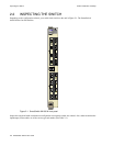
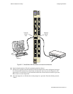
•• Plug one end of the supplied RJ-45 UTP cable into the 9-pin RJ-45 adapter (see Figure 2-3).
2p›F For information about adapter wiring configurations, see Appendix A,
"Specifications."
T• Plug the other end of the UTP cable into the SmartSwitch 9A100 female RJ-45 jack labeled
Terminal, located on the front panel (see Figure 2-3).
Q• Connect the switch to your network by plugging a UTP cable into the SmartSwitch 9A100 female
RJ-45 jack labeled Ethernet, located near the center of the switch's front panel (see Figure 2-3).