


SmartSwitch 9A100 User Guide 5-3
Troubleshooting Troubleshooting PNNI Links
5. Check whether BUS is connected.
• Use show busclient to check whether devices are registered with the BUS. If clients are registered,
check end node configuration. If not registered, check multi-point signaling.
• Use set leselan to turn off multi-point signaling on a per-ELAN basis.
- Do devices begin to register with the LES and BUS once multi-point signaling is turned off?
• Check IISP routes to the switch containing the LES and BUS.
- Are all IISP routes correct?
- Does a new IISP route need to be added so devices can reach the LES and BUS?
6. If working through these questions does not solve the problem, contact Cabletron Systems Customer
Service. (See Appendix C, “Technical Support.”)
5.3 TROUBLESHOOTING PNNI LINKS
You have physically connected another company’s ATM switch with your SmartSwitch 9A100. Each switch supports
PNNI, but there is no connectivity between the two devices. Use the following procedure to diagnose and resolve the
problem.
Examine the link state on each switch (
show PNNILink on SmartSwitch 9A100).
• If the link does not appear in the Link list, check the following:
- Is the connecting port on each switch configured for PNNI? If no, configure both ports for
PNNI.
Note On the SmartSwitch 9A100, use the show portconfig command to determine
whether the port is PNNI. If
show portconfig displays autoConfig as the port
configuration, use the
set portconfig command to disable ILMI and manually
set the port to PNNI.
- Examine the VCC masks for each switch. Are the switches using compatible VPI/VCI pairs? If
not, adjust the VCC mask so that both switches use compatible VPI/VCI pairs.
• If link state is “attempt,” check the following:
- Is the PNNI peer group ID the same on both switches? If not, set both peer group IDs to the same
value.
- Is the PNNI node ID the same for both switches? If not, set the PNNI node ID to the same value.
Especially check that the first two octets (peer-group level and lowest-level node) of the node
ID are the same for both switches.
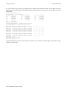
• If the link state is “2WayInside,” check the ATM route tables on each switch (show ATMRoute on
SmartSwitch 9A100).
- If the switches are supporting end systems or have clients, does the net prefix of each switch
appear in the ATM route table of the other?
If no, check both switches for signaling and ILMI misconfiguration.
If yes, contact Cabletron Systems Customer Service.