


SmartSwitch 9A100 User Guide 3-3
,6˜3¦F•˜":1˜"m=˜/"2' %•F"›amV˜"m˜'h¤d"›F=˜/"2˜˜
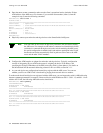
Note If configured devices fail to join the VLAN, see Chapter 4, Section 4.2.2, “UNI
Routes.” Also, see Chapter 5, Section 5.1, “Troubleshooting IP Over ATM.”
You have completed the process for creating an IP over ATM VLAN. Continue to the next section for instructions on
creating an emulated LAN or go to Chapter 4, “Switch Administration,” for information about SmartSwitch 9A100
switch operations and maintenance.
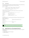
3.1.1 ATM Addressing for IP over ATM
The SmartSwitch 9A100 provides a default format for ATM addresses used by IP over ATM. The default format is
constructed as follows:
netprefix + two zero bytes + IP address of the device (in hex) + a trailing zero byte
Where the netprefix is constructed from
39 + nine zero bytes + the last three bytes of the device’s MAC address
For instance, if the switch’s MAC address is
00:20:D4:14:41:80 and
the switch’s client IP address is
90.1.1.1,
then
the
20
-byte ATM address of the ARP server is
39:00:00:00:00:00:00:00:00:00:14:41:80:00:00:5A:01:01:01:00
Where
39:00:00:00:00:00:00:00:00:00:14:41:80
= netprefix
00:00
= two trailing zeros
5A:01:01:01
= IP address 90.1.1.1 in hexadecimal
00
= trailing zeros byte
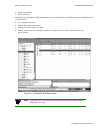
3.2 CREATING AN EMULATED LAN
This section describes the steps for implementing an Ethernet Emulated LAN (ELAN) on your SmartSwitch 9A100
switch. The following assumptions are made:
•
The SmartSwitch 9A100 switch will contain a client on the ELAN.
•
All end nodes (computers, edge devices, other switches, and so on) support the Well Known LECS
Address or can obtain the address of the LECS using ILMI.
•
All end nodes support Switched Virtual Circuits (SVCs).
Note An ELAN comes pre-configured on SmartSwitch 9A100 switches. The ELAN
name is “ELAN000.” To use this ELAN, start the LECS, configure your end nodes
and edge devices to use this ELAN000, and then plug them into the
SmartSwitch 9A100.