


4-8 SmartSwitch 9A100 User Guide
IP Routing Switch Administration
Note SmartSwitch 9A100 IP routing performance is inadequate for routing between
VLANs. If you need to create routes between VLANs on your
SmartSwitch 9A100, use a router equipped with an ATM interface. Consult
Cabletron Customer Support for recommended routers.
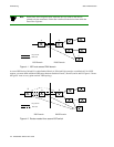
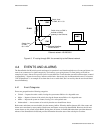
For example,
• Switch SW1 and the NMS are on an Ethernet network with address 128.205.99.0.
• The IP address of SW1's Ethernet port is 128.205.99.254.
• The IP address of SW1's LANE client is 90.1.1.254.
• The IP address of SW2's LANE client is 90.1.1.33.
• SW2 is not physically connected to the Ethernet network.
• SW2 is connected to SW1 through PNNI, and are both part of the same emulated LAN.
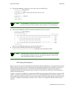
To reach SW2 with the Ethernet-based NMS, create an IP route that assigns SW1's switch client as SW2's default
gateway to the network 128.205.99.0. Enter the following on SW2 (see Figure 4-3):
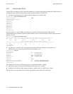
SmartSwitch # add route
DestNetIP() : 128.205.99.0
< address of the Ethernet network to reach
GatewayIP() : 90.1.1.254
< IP address of SW1's LANE client
SmartSwitch #
Switch SW2 can communicate with the NMS on the Ethernet network.
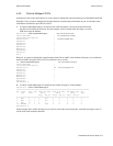
To see the route, enter the
show route command on SW2
SmartSwitch # show route
ROUTE NET TABLE
destination gateway flags Refcnt Use Interface
------------------------------------------------------------------------
0.0.0.0 0.0.0.0 1 0 0 zn0
90.1.1.0 90.1.1.33 1 0 1688 zn1
128.205.99.0 90.1.1.254 1 3 5660 ei0
------------------------------------------------------------------------
ROUTE HOST TABLE
destination gateway flags Refcnt Use Interface
------------------------------------------------------------------------
127.0.0.1 127.0.0.1 5 0 0 lo0
------------------------------------------------------------------------
SmartSwitch #
Note The NMS must contain a route that specifies the Ethernet interface of the Ethernet
connected switch as the gateway to the ELAN subnet.