


3-6 SmartSwitch 9A100 User Guide
%•F"›amV˜"m˜'h¤d"›F=˜/"2 ˜˜,6˜3¦F•˜":1˜"m=˜/"2'
3.2.1 ATM Addressing for LAN Emulation
The SmartSwitch 9A100 provides a default format for ATM addresses used by LAN emulation. The default format is
constructed as follows:
netprefix + the MAC address of the device + a Selector Byte
Where the netprefix is constructed from
39 + nine zero bytes + the last three bytes of the switch’s MAC address
The Selector Byte specifies to whom the ATM address belongs.
00
= LEC
01
= LECS
02
= LES or BUS
For instance, if the switch’s MAC address is
00:20:D4:14:41:80
, then the 20-byte ATM address of the LECS is:
39:00:00:00:00:00:00:00:00:00:14:41:80:
00:20:D4:14:41:80:01
Where
39:00:00:00:00:00:00:00:00:00:14:41:80 = netprefix
00:20:D4:14:41:80 = the switch’s MAC address
01 = the Selector Byte indicating that this is the LECS
Additionally, within both the LES and BUS addresses, the byte that corresponds to the last byte of the MAC address
is summed with the ELAN number. For example, the ATM address of the LESs on ELAN000, ELAN001, and
ELAN010 are
LES for ELAN000 =
39:00:00:00:00:00:00:00:00:00:14:41:80:00:20:D4:14:41:
80
:02
LES for ELAN001 =
39:00:00:00:00:00:00:00:00:00:14:41:80:00:20:D4:14:41:
81
:02
LES for ELAN010 =
39:00:00:00:00:00:00:00:00:00:14:41:80:00:20:D4:14:41:
8A
:02
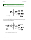
3.2.2 ELANs Across Multiple Switches
ELANs can exist within a single switch, or they can span multiple switches. When an ELAN spans multiple switches,
it’s important that all switches within the group use the same LECS. The general rule is: “Within an administrative
domain (a group of switches with related ELANs), there should be one and only one LECS.” For this reason, never
start the LECS on more than one switch within the administrative domain.
Note
If an uplink or end node does not support PNNI, or if its version of ILMI is
incompatible, it may be necessary to set up a static route between the device and
the rest of the ELAN. See Section 4.2, “ATM Routing.”