


10
SSIM-H2-02 Fast Ethernet - Translational Switch SmartStack Interface Module Installation and User Guide Installation
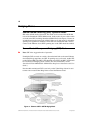
Cabling
The module uses standard or crossed-over UTP-5 copper cables. The maximum
cable length is 100 m (328 feet).
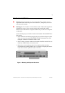
1. Insert the modular RJ-45 jack from either end of a standard or crossed-over
UTP-5 cable into one of the connectors on the SSIM-H2-02 front panel.
2. Connect the other end of the cable to:
— another TS port (using the crossed-over UTP-5 cable)
— 100/10 MB Ethernet adapter (using the crossed-over UTP-5 cable)
— 100/10 MB Ethernet switch or hub port (using the standard UTP-5 cable)
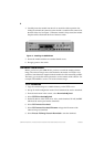
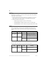
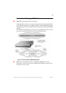
LEDs
There are eight LEDs on the front panel of the SSIM-H2-02. During normal
operation, the two LEDs on the left side of the front panel indicate the module
status:
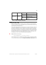
The three LEDs on the right of every port indicate the port status:
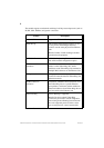
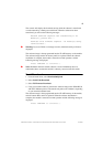
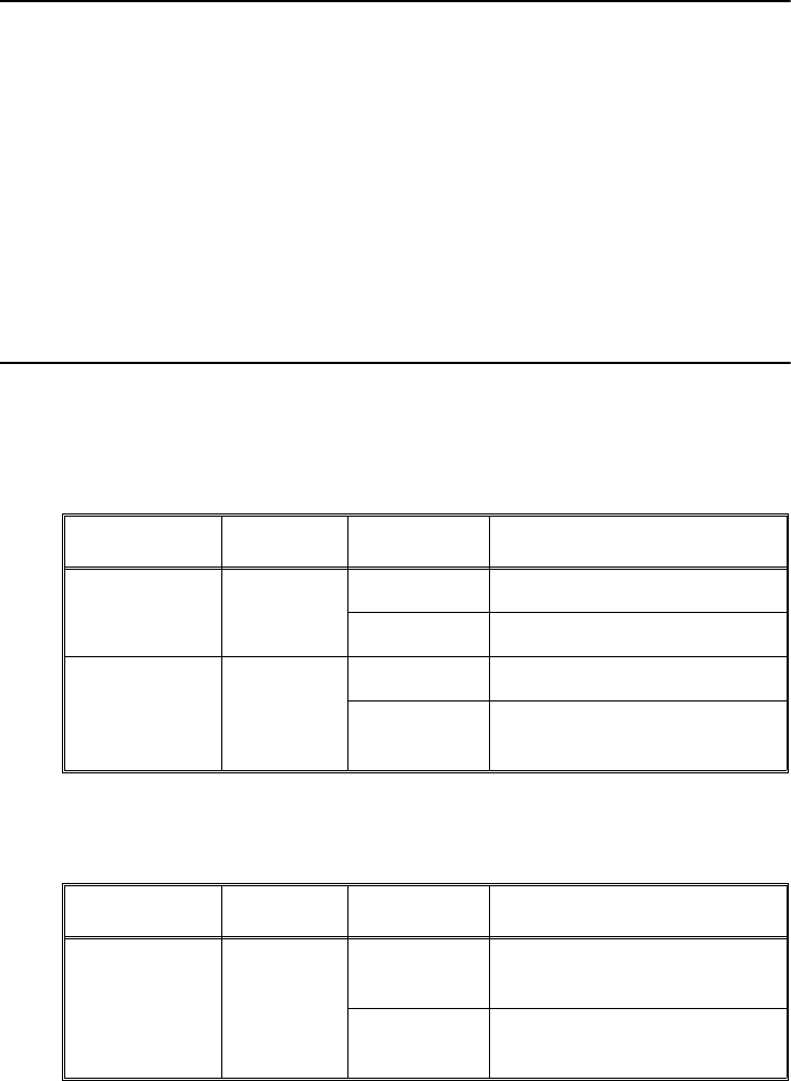
LED Position State Meaning
DIAG (green) Top
On
Diagnostics are in process.
Off
No diagnostics are in process.
ERR (yellow) Bottom
On
A module failure has occurred.
Off
The module is working
correctly.
Table 2. LEDs at the Left on the Front Panel
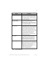
LED Position State Meaning
ACTIVITY
(green)
Top
Flashing
The port is receiving or
transmitting frames.
Off
Currently no traffic on the port.
Table 3. LEDs at the Right of Every Port