


E&M Signaling Conventions
9/24/01 11-3
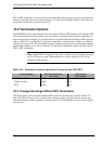
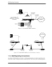
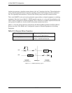
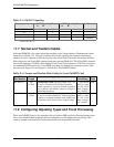
Figure 11-1: Normal Mode E&M Termination
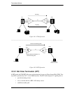
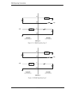
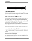
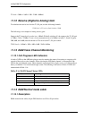
Figure 11-2: Tandem Mode E&M Access to Leased Lines or Carriers
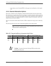
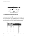
11.4 E&M Signaling Conventions
According to E&M signaling conventions, switching equipment always originates signaling on the
M-lead (the “mouth” sending toward the transmission line). The E-lead of the switching equipment
Public or Private
Network
Analog PBX
Modem for Data
Dedicated Transmission
Only
4-Wire E&M
Normal Mode
Access Bank I
T1 Network
Connection
Stations
4-Wire E&M
TO Mode
Up to 24 E&M or TO
Interfaces in 12 Channel
Increments
PBX
Radio or Micro-
Wave tower
Radio or Micro-
Wave tower
Radio or Microwave
Transceiver
Radio or Microwave
Transceiver
Carrier Network
Access Bank I
Access Bank I
T1
T1
4-Wire E&M
Tandem
Mode
4
-
W
i
r
e
E
&
M
Tandem
Mode