


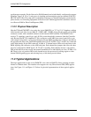


4-Wire E&M/TO Configuration
11-10 9/24/01
T1 level = 3dBm + 16dB + 2dB - 21dB = 0dBm0
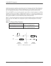
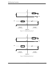
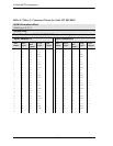
11.12 Receive (Digital-to-Analog) Gain
To calculate the receive level on the T1, R1 pair, use the following formula:
T1/R1 level = T1 level +åGain Switches -21dB
The following is an example of setting receive gain:
Suppose the T1 input level to codec is at -1dBm0. With all switches off, the output at the T1, R1 pair
is -1dBm -21db = -22dBm. To set a 4-wire transmission level of 0dBm, switches 7, 9 and 10 (gains
2dB, 8dB, and 16dB) must be turned on. The level at the T1, R1 pair is then:
T1/R1 level = -1dBm0 + 2dB + 8dB +16dB -21dB = 0dBm.
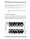
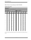
11.13 E&M Voice Channel Monitoring
11.13.1 Call Progress LED Indicators
A bank of LEDs on the ABI back plate are used to monitor the status of incoming or outgoing calls
on each of the twelve voice channels. When viewing the LED bank, channel 1 corresponds to the
LED in the top left hand corner. Other channels are arranged left to right, row by row (like reading a
book), so channel 12 is in the bottom right corner. The meaning of the states of these 12 LEDs are
summarized in Table 11-6.
Table 11-6: E&M Channel Status LEDs
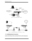
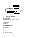
11.14 E&M Normal mode cable
11.14.1 Description
E&M normal mode cable, 96-pin DIN female to two Telco 50-pin males.
LED State Meaning
Off Idle state
Green Analog side is Off Hook
Red Digital side is Off Hook
Yellow Analog and Digital sides are both Off Hook