


12-14 9/24/01
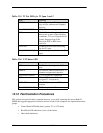
Table 12-5: T1 Test LEDs for T1 Span 1 and 2
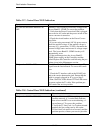
Table 12-6: V.35 Status LED
12.12 Fault Isolation Procedures
This section lists typical trouble symptoms that may occur while operating the Access Bank II -
SNMP and suggests appropriate corrective actions to take. Fault symptoms are organized into three
groups:
• Control Panel LED indications (system, T1 or V.35 faults)
• Back Plate LED indications (voice circuit faults)
• Other fault indications
State Meaning
GREEN Normal operations. Trunk process-
ing, self test, and network loopback
inactive.
FLASHING GREEN T1 Self Test local loopback passed.
RED T1 Self Test local loopback failed
due to one or more of the following
conditions: T1 Loss of Signal, Out of
Frame, Improper Line Code
Received, ESF or BPV errors
received.
YELLOW Channels held in Trunk Processing
for this T1 span.
FLASHING YELLOW Network loopback active for this T1
span.
State Meaning
OFF No T1 channels assigned to V.35
port.
GREEN CD (RLSD) and RTS leads active. T1
channels assigned and operative.
FLASHING GREEN V.35 in loopback to equipment.
RED CD (RLSD) lead is inactive because
assigned T1 is inoperative.
YELLOW CD (RLSD) lead active. RTS lead
inactive.
FLASHING YELLOW V.35 in loopback to T1 line.