


Control Panel DIP Switches
9/24/01 2-3
• Three-position DC power terminal input for connection to the 115 Vac to -48 Vdc Power
Converter Cube, or to a customer-supplied external -48 Vdc battery power source.
• Tip & Ring Analog Interface equipped with standard 25-pair Telephony Connector
(female) for connection to key systems, facsimile devices, modems and PBXs.
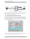
The ABII Control Panel is equipped with an interface connector for accessing the embedded SNMP
agent.
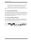
2.4 Control Panel DIP Switches
The Access Bank II - SNMP Control Panel also contains a 10-position T1 Span Setup DIP switch that
is used for individually configuring each of the two T1 network interfaces. There is also a 4-position
System Setup DIP switch for selecting between Local or Remote modes of management and activat-
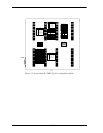
ing and deactivating alarm cut-off. The locations of these DIP switches are shown in Figure 2-1. As
an aid to setting up the these DIP switches, a convenient installation guide is silk screened onto the
chassis housing and reprinted here in Figure 2-2.
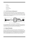
2.5 LED Test and Status Indicators
There are five LED indicators that display the current performance and test status of the dual T1
spans lines and V.35 digital interface. Figure 2-1 shows the locations of these LEDs on the Access
Bank II - SNMP front Control Panel. How to interpret the current state of each LED indicator is silk
screened onto the chassis housing and reprinted here in Figure 2-2.
Figure 2-1: Access Bank II - SNMP Control Panel
T1
Span 1
T1
Span 1
T1 Span Setup
Self Test 1
Network Loopback 1
T1 Framing 1
T1 Line Code 1
CSU On/Off 1
Self Test 2
Network Loopback 2
T1 Framing 2
T1 Line Code 2
CSU On/Off 2
System Setup
SNMP/TELNET