


Connecting the Power and Ground
9/24/01 5-13
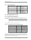
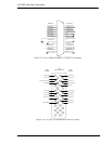
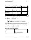
Table 5-8: CAC Straight Adapter Pin Assignments
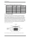
5.8 Connecting the Power and Ground
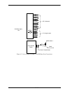
5.8.1 DC Power Connector Input
Warning: Connect only -48 Vdc power to the DC input connector.
The Access Bank II SNMP has a 3-position DC Power Connector Input located on the Control Panel,
as shown in Figure 5-1. To conform with UL 1459 and National Electrical Code safety requirements,
the Access Bank II SNMP is equipped with solid-state, automatic-resetting, current-limiting devices
to protect the -48V Input and +DC Return power inputs on this connector from AC power surges,
lightning, or inductive motor spikes. This means there are no internal fuses for you to replace.
Pinout assignments for this connector are defined in Table 5-9.
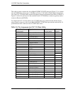
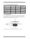
Table 5-9: Power Connector Pinout Assignments
Designation DCE DB9 female DCE DB25 male Pair Signals
(Not required)
Shield + (Shield) 1+ (Shield)
Ground 5 7
Secondary TXD 3 2
Secondary RXD 2 3 °
Secondary RTS 7 4
66 °
Secondary DTR 4 20
85 °
Secondary CD 1 8 °
922
Pin Number Signal
1 AB115 Power Converter Cube, or -42 to -58 Vdc
power source
2 DC return, to power supply + terminal
3 Telco or safety (green-wire) ground
!