


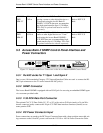
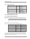
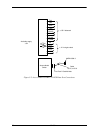

Access Bank II SNMP Control Panel Interface and Power Connectors
9/24/01 5-3
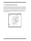
5.3 Access Bank II SNMP Control Panel Interface and
Power Connectors
Figure 5-1: Interface and Power Connectors on the Access Bank II SNMP Control Panel.
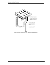
5.3.1 RJ-48C Jacks for T1 Span 1 and Span 2
One (or two) 10-foot modular Category 5 T1 Network Interface Cables are used to connect the RJ-
48C 8-pin connectors to the T1 carrier network RJ-48C jack(s).
5.3.2 SNMP Connector
The Access Bank II SNMP is equipped with an RJ-45 jack for accessing an embedded SNMP agent
via a customer provided cable.
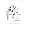
5.3.3 V.35 DCE Data Port Connector
The optional CAC V.35 Data Cable (10’, 25’ or 50’) with a micro-D 26-pin (male) to 34-pin Win-
chester connector (male) connects this 26-pin V.35 DCE data interface connector (female) to cus-
tomer premise DTE.
5.3.4 DC Power Connector Input
Power connections are made to the DC Power Connector Input with a three-position removable wir-
ing connector on the 8-foot DC power cord from the 115 Vac to -48 Vdc Power Conversion Cube.
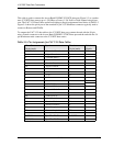
005-0009-
DCE-
MM-25’
25 foot,
7.62 m
Twenty-five-foot V.35 Data Cable for con-
necting a router or other digital device to a
T1 network using the Access Bank II
SNMP’s V.35 DCE data port, accommodat-
ing high-speed transfers up to 1.536 Mbps.
This cable is optional and must be ordered
separately.
Fine Pitch D-Sub-26
Male to DCE V.35
Male
005-0010-
DCE-
MM-50’
50 foot,
15.24 m
Fifty-foot V.35 Data Cable for connecting a
router or other digital device to a T1 net-
work using the Access Bank II SNMP’s
V.35 DCE data port, accommodating high-
speed transfers up to 1.536 Mbps. This cable
is optional and must be ordered separately.
Fine Pitch D-Sub-26
Male to DCE V.35
Male
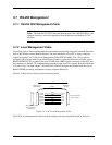
T1
Span 1
T1
Span 1
T1 Span Setup
Self Test 1
Network Loopback 1
T1 Framing 1
T1 Line Code 1
CSU On/Off 1
Self Test 2
Network Loopback 2
T1 Framing 2
T1 Line Code 2
CSU On/Off 2
System Setup
SNMP/TELNET