


3-4 9/24/01
defined signaling options.)
• DC Loop Range: 1200 ohms (3 miles on 24 AWG + 300 ohms telephone)
• Loop Feed: Nominal -48 Vdc with 30 mA current limit
• Separate Transmit/Receive Gain Settings on a Per Channel Basis
• All-channel simultaneous ringing power: 85 Vrms at 20 Hz
• Built-in ringback tones
• Battery Reversal FXS/DPO Voice Card
• FXS Loop Start with Battery Reversal or Dial Pulse Originating (DPO) functionality per
card
• Optional Cadenced Ringback Tone (two-seconds on, four seconds off) to the T1 line dur-
ing incoming calls, synchronized to the ringing voltage present on the loop
• Optional Cadenced Ringing Voltage applied to CPE loop during an incoming call
• Supports CLASS® services, including Caller ID
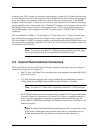
3.11 FXO/DPT Voice Card
• FXO Loop-Start/Ground-Start terminations per channel
• Dial Pulse Termination (DPT) functionality per card
• Separate transmit and receive gain settings per channel
• DID and DNIS carrier services
• CLASS® services, including distinctive ringing and caller ID
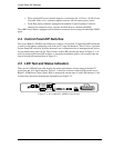
3.12 4-Wire E&M/TO Voice Card
• Optioned with on-board jumpers to support E&M signaling types I, II, IV, or V, for each
channel
• Supports Transmission Only (TO) for dedicated modems, radio/paging systems, etc.
• Separate gain and loss settings from +10 dB to -21 dB for both transmit and receive paths
for each channel
• Maximum analog transmission level of +9.5 dBm
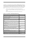
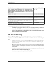
3.13 Network Management
• RS-232 Primary Management Port, Cable, Command Line Interface, and MS Windows-
based Remote Monitor Graphical User Interface (GUI) software program included with