


Connecting the Dual T1 Lines
9/24/01 5-5
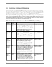
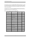
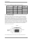
Table 5-2: 50-Pin Tip & Ring Jack
5.5 Connecting the Dual T1 Lines
5.5.1 Customer Premises Installations
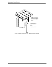
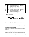
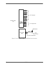
Connections to the T1 network interfaces are made at the RJ-48C 8-pin modular jacks on the Access
Bank II SNMP Control Panel (see Figure 5-1) using one (or two) 10-foot Category 5 T1 cable(s).
Note: Only one T1 network interface cable is provided with each unit. Additional
cables (P/N 005-0009) are available from distributors or dealers of CAC products.
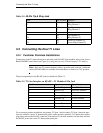
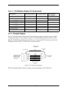
The pin assignments for the RJ-48C jacks are defined in Table 5-3.
Table 5-3: T1 Line Interface on RJ-48C—T1 Modular 8-Pin Jack
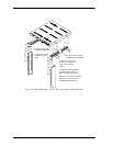
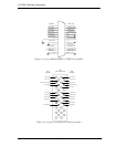
For a customer premise installation, the primary T1 Span 1 and secondary T1 Span 2 network inter-
faces are cabled to carrier T1 demarcation points on the customer premises. To connect these cables,
plug either end into the RJ-48C connector of the desired T1 network interface and the other end into
the RJ-48C jack at the carrier T1 demarcation point jack.
Pair Pin Location Function
1
26
1
Tip Channel 1
Ring Channel 1
2
27
2
Tip Channel 2
Ring Channel 2
↓↓↓
24
49
24
Tip Channel 24
Ring Channel 24
25
50
25
Alarm Tip Channel 25
Alarm Ring Channel 25
Pin Number Signal Signal Direction
1 Receive Ring From DS1 Network
2 Receive Tip From DS1 Network
3 No connection
4 Transmit Ring To DS1 Network
5 Transmit Tip To DS1 Network
6 No connection
7 Receive Ground
8 Transmit Ground