


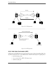


12-Channel FXO & Dial Pulse Termination Card
10-2 9/24/01
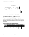
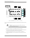
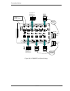
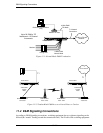
FXO or DPT termination. Also on the card, each individual channel has a two position switch for the
selection of ground start or loop start (see Figure 9-3) and a 6-section DIP switch to control the line
attenuation (see Channel Attenuation Options).
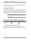
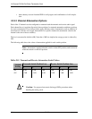
10.3 Termination Options
The FXO/DPT card can be configured for use as either an FXO or DPT interface card. Further, FXO
offers both ground start (GS) and loop start (LS) modes of operation. These options require the set-
ting of one switch per channel (12 per card) and one 4-position Dual Inline Package (DIP) switch per
card (see Table 10-1, and Figure 9-3). Note that in the table, a 1 indicates the switch is on, while a 0
indicates the switch is off. The slide switch on the 12-channel analog card for each channel indicates
whether that channel is set to GS or LS mode. The DIP switch determines whether the card will use
FXO or DPT termination.
Note: When DPT is selected, the large slide switches for each channel must all be
set to LS. However, when FXO termination is chosen, either LS or GS can be
selected for each channel.
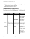
Table 10-1: Termination Options and Switch Settings for the FXO/DPT
10.3.1 Foreign Exchange Office (FXO) Termination
The FXO provides private branch exchange (PBX) office end connectivity to public network T1
lines. The FXO acts as a sink for a battery source, detects ringing, provides outgoing seizure, pro-
vides and interprets A/B bit signaling to and from the T1 line, and enables two-way voice frequency
transmission.
Trunk Signaling
4-Position DIP Switch
per Card
Slide Switch
per Channel
FXO Ground Start 0000 GS
FXO Loop Start 0000 LS
DPT 1000 LS