


Fault Isolation Procedures
9/24/01 12-15
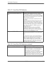
Table 12-7: Control Panel LED Indications
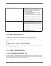
Table 12-8: Control Panel LED Indications (continued)
Symptom Corrective Action
All LED test and status indicators are
OFF.
Indicates a loss of power or excessive voltage to the
Access Bank II - SNMP. To correct the problem:
1 Verify that the Power Conversion Cube is plugged
into an active AC outlet and the power switch on the
power converter is turned on.
2 Check the circuit breaker on the Power Conver-
sion Cube.
3 If you are using an external -48 Vdc power source,
check the applied voltage. If the applied voltage is
incorrect (e.g., greater than -70 Vdc), disconnect the
external voltage source and correct its voltage output
level. The Access Bank II - SNMP circuitry will
automatically reset.
4 If the problem persists, the Access Bank II -
SNMP power supply on the Controller card has
failed. Replace the Controller card following the pro-
cedure given in the Maintenance section.
T1 Span 1 or 2 LED is RED. The Access Bank II - SNMP is not receiving a T1
signal from the line indicated. To correct this condi-
tion:
1 Check the T1 interface cable at the RJ-48C jack
and at the carrier demarcation jack. Ensure that the
cable is properly plugged in. If so, go to Step 2.
2 Run a Self Test. If the affected T1 Test LED comes
up green, replace the T1 cable. If the problem per-
sists contact the service provider.
Symptom Corrective Action
T1 Span 1 or 2 LED is YELLOW. . Bipolar Violations (BPVs) are being received
from the network. A 1-second flash indicates
that at least one BPV was received during a 1-
second interval. To correct this problem:
1 Verify the T1 Line Code 1 or 2 option selected
matches the line coding sent by the carrier.
2 If the Line Code option is set correctly and the
problem persists, contact your service provider.