


17-10
Cisco ONS 15600 Procedure Guide, R8.0
Chapter 17 DLPs E100 to E199
DLP- E109 Drill Holes to Anchor and Provide Access to the Bay Assembly
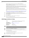
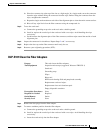
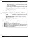
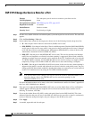
Figure 17-1 Floor Template
Step 2
Use the corner indicators “C” to determine the closest recommended position of an adjacent 900-mm
(35.4-inch) bay assembly.
Step 3 Use a marking pen to mark the floor with the corner indicators appropriate to your installation.
Step 4 At the four locations marked “D,” drill floor bolt holes according to the bolt manufacturer’s
recommendation for bolt hole size.
Step 5 If you will use under-floor power, use the drill and saw to cut out the rectangular floor areas marked “E.”
Step 6 If you will route optical cables in a 900-mm (35.4-inch) bay from under the floor, use the drill and saw
to cut out the rectangular floor areas marked “F.”
Step 7 If you will route optical cables in a 600-mm (23.6-inch) bay from under the floor, use the drill and saw
to cut out the rectangular floor areas marked “J.”
Step 8 If you will route any timing, alarm, or LAN cables through the floor to the customer access panel (CAP),
use the drill to cut out the floor areas marked “G.”
Step 9 (Optional.) If you want to create other access holes for under-floor access (for AC power, for example),
use the reciprocating saw to cut sufficient holes within any of the locations marked “H.”
Step 10 Return to your originating procedure (NTP).
83488
C B
AA
BC
G
G
D
H
H
H H
F
F
E E
D
C B
AA
BC
J
J
D
H
FRONT
H
F
F
D
UNDERFLOOR SYSTEM CABLE UNDERFLOOR SYSTEM CABLE
UNDERFLOOR CMP CABLE UNDERFLOOR CMP CABLEOPTICAL CABLE ACCESS
OPTICAL CABLE ACCESS
OPTICAL CABLE ACCESS
UNDERFLOOR POWER UNDERFLOOR POWER
UNDERFLOOR NETWORK CABLEUNDERFLOOR NETWORK CABLE
CABLE ROUTING MODULECABLE ROUTING MODULE ADJACENT RACKADJACENT RACK
Bolt Hole
Pattern
600 mm Footprint
900 mm Footprint
Adjacent Rack