


4011533 Rev A 117
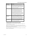
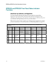
DPR2320 and EPR2320 Front Panel Status Indicator Functions
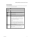
Normal Operations
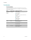
The following chart illustrates the appearance of the cable modem front panel LED
status indicators during normal operations.
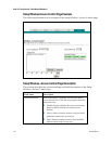
Step 8
DPR 2320 and EPR2320 Front Panel LED Status Indicators During Normal
Operations
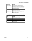
Front Panel
Indicator
Normal Operations
1 Power ON
2 Receive
BLINKS - To indicate data is being transferred between the
modem and the network
3 Send
BLINKS - To indicate data is being transferred between the
modem and the network
4 Cable ON
5 PC
ON - When a single device is connected to either the Ethernet or
USB port and no data is being sent to or from the modem
BLINKS - When only one Ethernet or USB device is connected
and data is being transferred between the consumer premise
equipment (CPE) and the cable modem
OFF- When no devices are connected to either the Ethernet or
USB ports
Note: With both Ethernet and USB devices connected to the
modem at the same time, when data is being transferred through
only one of the devices (Ethernet or USB), the indicator will
illuminate continuously. Whenever data is being sent through
both data ports (Ethernet and USB) simultaneously, the indicator
will blink as described above.
6 Wireless
ON - When the wireless access point is operational
BLINKS - To indicate data is being transmitted through the
wireless access point
OFF - When the user disables the wireless access point