


16 4011533 Rev A
DPR2325 and EPR2325 Back Panel Description
DPR2325 and EPR2325 Back Panel Description
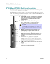
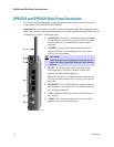
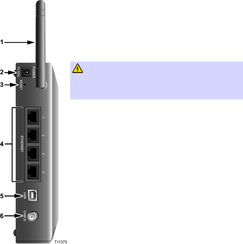
The following illustration shows the description and function of the back panel
components of the DPR2325 and EPR2325.
Important! Do not connect your PC to both the Ethernet and USB ports at the same
time. Your modem will not function properly if both the Ethernet and USB ports are
connected to your PC at the same time.
1 ANTENNA—Provides a communication connection
for the built-in wireless access point (WAP) to allow
wireless devices to communicate with the cable
modem
2 POWER—Connects the cable modem to the DC
output of the AC power adapter that is provided
with your cable modem
CAUTION:
Avoid damage to your equipment. Only use the AC
power cord that is provided with your cable modem
gateway.
3 RESET—Activating this switch resets the cable
modem gateway to factory default values and
reboots the cable modem gateway
Note: This switch is for maintenance purposes only.
Do not use unless directed to do so by your service
provider.
4 ETHERNET—Four RJ-45 Ethernet ports connect to
the Ethernet port on your PC or to an Ethernet hub
on your home network
5 USB—12 Mbps USB port connects to the USB port
on your PC
6 CABLE—F-Connector connects to an active cable
signal from your service provider