


B-12
Catalyst 4948E an Catalyst 4948E-F Switch Installation Guide
OL-21561-02
Appendix B Transceiver, Chassis Connectors, and Cable and Adapter Specifications
Ethernet Management Port
The two-color LINK LED associated with the console port provides visual status for the port:
• Green—Link is established
• Amber—Administrative disabled
• Off—No link is detected
Ethernet Management Port
The Ethernet management port supports10/100/1000BASE-T Ethernet. It can autonegotiate to operate
at any line speed (10, 100, 1000 Mbps); full and half duplex modes for 10 and 100 Mbps line speed, and
only full duplex at 1000 Mbps. The Ethernet management port has an RJ-45 connector with an associated
Link Status LED.
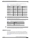
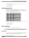
Table B-15 lists the 10/100BASE-T port pinouts.
The two-color LINK LED associated with the Ethernet management port provides visual status for the
port:
• Green—Link is established.
• Amber—Administrative disabled.
• Off—No link is detected.
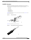
Cables and Adapters
One cable adapter plug is supplied in the accessory kit for both switches.
Note A console cable is not provided in the accessory kit. It can be ordered as an option.
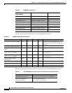
Rollover Cable
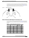
You can use an optional RJ-45 rollover cable and the supplied RJ-45/DSUB F/F adapter to connect the
chassis console port to a computer running terminal emulation software. Table C-2 lists the pinouts for
the console port, the RJ-45 rollover cable, and the RJ-45/DSUB F/F adapter.
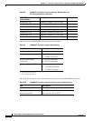
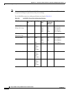
Ta b l e B-15 10/100/1000BASE-T Ethernet Management Port Pinout
Pin Signal Direction Description
1 RXDP input receive data
2 RXDN input receive data
3 TXDP output transmit data
4 unused — —
5 unused — —
6 TXDN output transmit data
7 unused — —
8 unused — —