


3-21
Catalyst 4948E and Catalyst 4948E-F Switch Installation Guide
OL-21561-02
Chapter 3 Installing the Switch
Powering Up the Switch
Powering Up the Switch
This section provides a quick power-up procedure for a switch. The section is divided into the following
topics:
• Starting the Terminal-Emulation Software, page 3-21
• Powering Up the Switch, page 3-21
Starting the Terminal-Emulation Software
Before you power-up the switch, start the terminal-emulation session so that you can see the output
display from the power-on self-test (POST).
The terminal-emulation software, which is frequently a PC application such as Hyperterminal or
ProcommPlus, makes communication between the switch and your PC or terminal possible.
To start the terminal-emulation software, follow these steps:
Step 1 Start the terminal-emulation program if you are using a PC or terminal.
Step 2 Start a terminal-emulation session.
Step 3 Configure the baud rate and character format of the PC or terminal to match these console port default
characteristics:
• 9600 baud
• 8 data bits
• 1 stop bit
• No parity
• None (flow control)
Powering Up the Switch
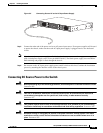
If your chassis has AC-input power supplies installed, follow these steps to power up the chassis:
Step 1 Switch the power supply power switches to the ON position.
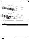
Step 2 Verify power supplies are operating correctly by looking at the INPUT OK and the OUTPUT OK LEDs
located on the power supply faceplate. The LEDs should be green when the power supply and the power
supply fan are functioning normally.
Also verify that the front panel PS1 LED is lit green. If the chassis is equipped with a second (redundant)
power supply, verify that the front panel PS2 LED is also lit green. If the LEDs are not green, refer to
the
“300 W AC-Input Power Supply (PWR-C49E-300AC-R)” section on page A-1 or “300 W AC-Input
Power Supply (PWR-C49E-300AC-F)” section on page A-5 for additional LED descriptions.