


3-15
Catalyst 4948E and Catalyst 4948E-F Switch Installation Guide
OL-21561-02
Chapter 3 Installing the Switch
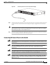
Attaching the Interface Cables
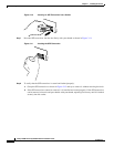
Step 9 Do not turn source DC power on at this time. Continue the installation process by attaching the interface
cables to the chassis ports.
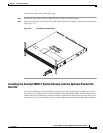
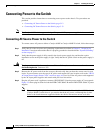
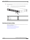
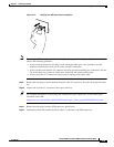
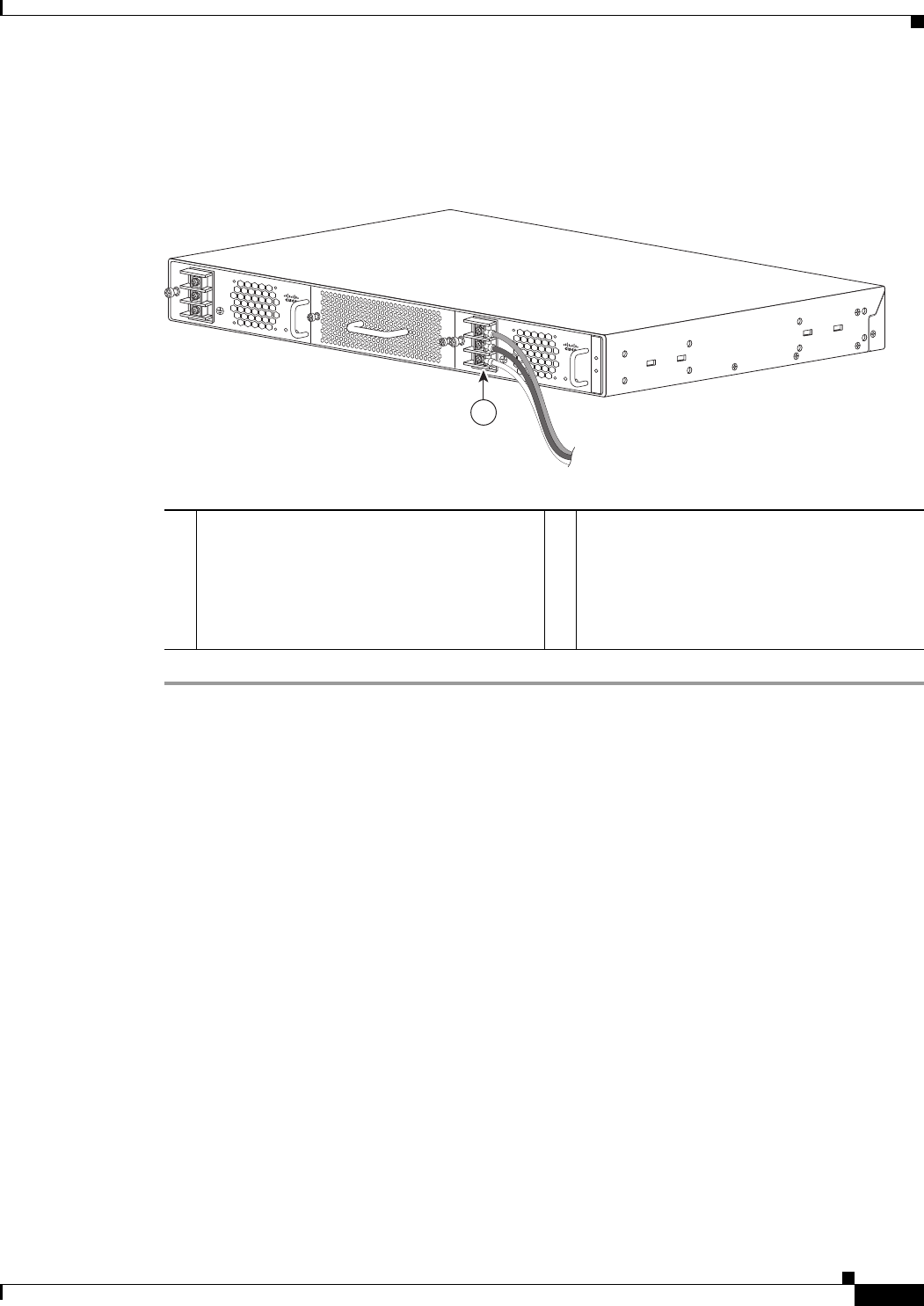
Figure 3-6 Connecting Source DC to the DC-Input Power Supply (PWR-C49-300DC)
Attaching the Interface Cables
This section covers attaching the interface cables to the chassis front panel connectors. The section is
divided into the following topics:
Connecting to the Downlink Ports, page 3-16
Installing Uplink Port Transceivers and Cables, page 3-16
Connecting to the Ethernet Management Port, page 3-20
Connecting to the Console Port, page 3-20
1 Attach the source DC leads to the power
supply terminal block in the following order:
• Ground
• (–) negative
• (+) positive
207517
INPUT
OK
OUTPUT
OK
PWR - C49-300DC
-48 To -60VAC
8A
+
-
+
-
INPUT
OK
OUTPUT
OK
PWR - C49-300DC
-48 To -60VAC
8A
1