


4-11
Catalyst 4948E and Catalyst 4948E-F Switch Installation Guide
OL-21561-02
Chapter 4 Removal and Replacement Procedures
Removing and Installing the Fan Tray
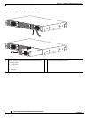
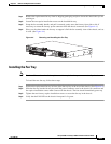
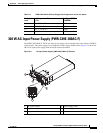
Step 1 Remove the replacement fan tray from its shipping packaging and place it near the chassis that you are
working on.
Step 2 Loosen the two captive installation screws on the installed fan tray.
Step 3 Grasp the fan assembly handle, and pull it outward; gently move the fan tray from side to side, if
necessary, to unseat the fan tray power connector from the chassis connector. (See
Figure 4-4.)
Step 4 Place your free hand under the fan tray to support it. Pull the fan assembly clear of the chassis, and set
it aside. (See
Figure 4-4.)
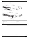
Figure 4-4 Removing and Installing the Fan Tray
Installing the Fan Tray
Note You have 30 seconds to install the replacement fan tray before the system automatically shuts down.
To install the new fan tray, follow these steps:
Step 1 Position the replacement fan tray in front of the fan tray bay at the rear of the chassis. (See Figure 4-4.)
Step 2 Slide the fan tray into the fan tray bay until the power connector seats in the chassis fan connector and
the captive installation screws make contact with the chassis. The fans should immediately power up.
Step 3 Tighten the two fan tray captive installation screws to secure the fan tray in the chassis.
Step 4 Verify that the FAN LED on the chassis front panel is lit green.
278174
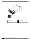
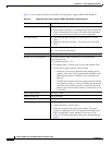
INPUT
OK
OUTPUT
OK
PWR - 540 AC
100 - 240 VAC
7 - 3A
50 - 60 Hz
INPUT
OK
OUTPUT
OK
PWR - 540 AC
100 - 240 VAC
7 - 3A
50 - 60 Hz