


4-5
Catalyst 4948E and Catalyst 4948E-F Switch Installation Guide
OL-21561-02
Chapter 4 Removal and Replacement Procedures
Removing and Installing the DC-Input Power Supply
Installing the DC-Input Power Supply
Warning
Before performing any of the following procedures, ensure that power is removed from the DC
circuits. To ensure that all power is removed, locate the circuit breakers or fuses on the DC power
lines that service the DC circuits. Turn OFF the DC power line circuit breakers and remove the DC
power line fuses.
Statement 322
Warning
When installing or replacing the unit, the ground connection must always be made first and
disconnected last.
Statement 1046
To install a DC-input power supply in the Catalyst 4948E switch, follow these steps:
Step 1 Ensure that the system (earth) ground chassis connection has been made.
Step 2 Verify that power is off to the DC circuit that feeds the power supply that you are installing.
As an added precaution, place the appropriate safety flag and lockout devices at the source power circuit
breaker, or place a piece of adhesive tape over the circuit breaker handle to prevent accidental power
restoration while you are working on the circuit.
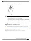
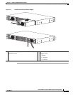
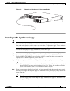
Step 3 Remove the new DC-input power supply from its protective packaging.
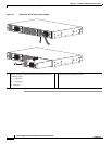
Step 4 Grasp the power supply handle with one hand, and place your other hand underneath the power supply.
Slide the power supply into the power supply bay until the power supply makes contact with the chassis
power connector. (See
Figure 4-2.) Press firmly on the power supply faceplate to fully seat the power
supply in the bay.
Note The DC power supply is equipped with an EMI gasket on the top, bottom, and sides (on the front
edge) of the power supply. When sliding the power supply into the power supply bay, be careful
not to damage the EMI gaskets.
Step 5 Tighten the power supply captive installation screw.
Step 6 Remove the plastic cover from the terminal block.
Step 7 Attach the appropriate lugs to the source DC wires.
Either insulated crimp-on spade lugs or insulated crimp-on ring connectors can be used on the source
DC cables. They should be sized according to local and national installation requirements and electrical
codes.
Note The wire should be sized according to local and national installation requirements and electrical
codes. Use only copper wire.