


1-11
Catalyst 4948E and Catalyst 4948E-F Switch Installation Guide
OL-21561-02
Chapter 1 Product Overview
Front Panel LEDs
Front Panel LEDs
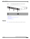
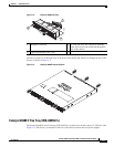
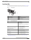
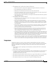
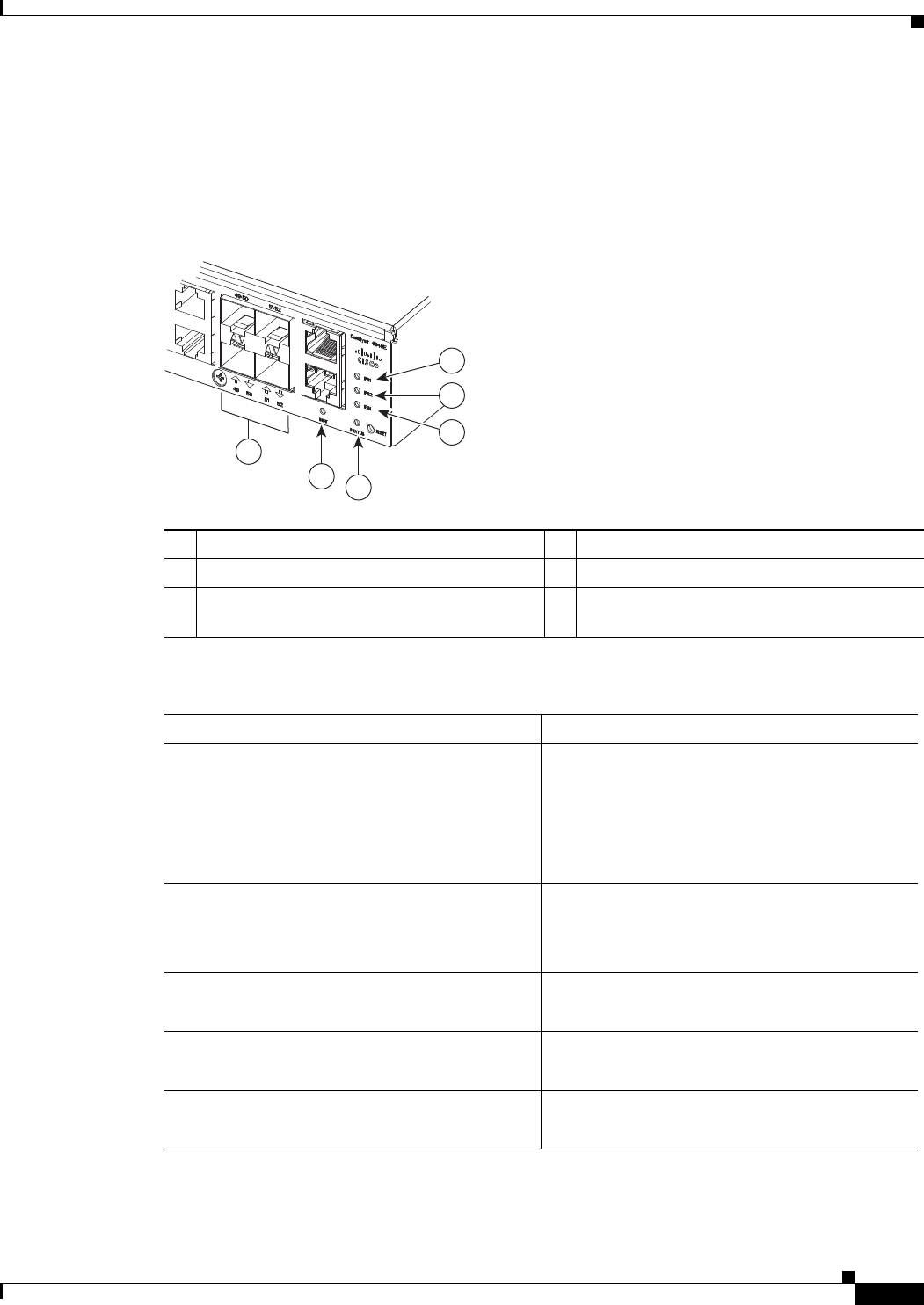
A set of LEDs on the chassis front panel provide visual status for the switch. (See Figure 1-7.) Table 1-5
lists the Catalyst 4948E and Catalyst 4948E-F switch chassis front panel LEDs and their meanings.
Figure 1-7 Front Panel LEDs
1 PS1 (power supply 1) 4 STATUS
2 PS2 (power supply 2) 5 MGT (management port LED)
3 FAN (fan tray) 6 LINK (port status). One LED for each uplink
and downlink port.
Ta b l e 1-5 Front Panel LED Descriptions
LED State and Meaning
STATUS Green—The system is up and running.
Red—System fault.
Flashing amber—Power-on self-test (POST) boot
up.
Off—System is not powered up.
LINK
48 10/100/1000 downlink port LEDs and 4
SFP/SFP+ uplink port LEDs
Green—Link is established.
Amber—Administrative disabled.
Off—No link is detected.
FAN
(Fan tray)
Green—Fan tray OK.
Red—One or more fan failures.
PS1
(Power supply 1)
1
1. There are three additional LEDs mounted on the power supply front panel that provide power supply status. These LEDs are
only visible from the back of the chassis. For a description of the LEDs, see the
“300 W AC-Input Power Supply
(PWR-C49E-300AC-R)” section on page A-1.
Green—AC-input or DC-input power is OK.
Red—Power supply fault detected.
PS2
(Power supply 2)
1
Green—AC-input or DC-input power is OK.
Red—Power supply fault detected.
278086
1
2
4
5
3
6