


B-13
Catalyst 4948E an Catalyst 4948E-F Switch Installation Guide
OL-21561-02
Appendix B Transceiver, Chassis Connectors, and Cable and Adapter Specifications
Cables and Adapters
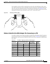
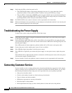
You can identify a rollover cable by comparing the two ends of the cable. Holding the cables side by
side, with the tab at the back, the wire connected to the pin on the outside of the left plug should be the
same color as the wire connected to the pin on the outside of the right plug. (See
Figure B-5.) If your
cable was purchased from Cisco Systems, pin 1 will be white on one connector, and pin 8 will be white
on the other. (A rollover cable reverses pins 1 and 8, 2 and 7, 3 and 6, and 4 and 5.)
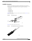
Figure B-5 Identifying a Rollover Cable
Rollover Cable RJ-45 to DB-9 Adapter (For Connecting to a PC)
Use an RJ-45-to-RJ-45 rollover cable and the RJ-45-to-DB-9 female DTE adapter (labeled Terminal) to
connect the console port to a PC running terminal emulation software.
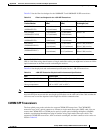
Table B-16 lists the pinouts for
the asynchronous serial console port, the RJ-45-to-RJ-45 rollover cable, and the RJ-45-to-DB-9 female
DTE adapter.
Pin 1
Pin 8
H3824
Pin 1 and pin 8
should be the
same color
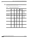
Ta b l e B-16 Port Mode 1 Signaling and Pinouts (DB-9 Adapter)
Console Port RJ-45-to-RJ-45 Rollover Cable RJ-45-to-DB-9
Terminal Adapter
Console
Device
Signal RJ-45 Pin RJ-45 Pin DB-9 Pin Signal
RTS 1
1
1. Pin 1 is connected internally to Pin 8.
8 8 CTS
DTR 2 7 6 DSR
TxD 3 6 2 RxD
GND 4 5 5 GND
GND 5 4 5 GND
RxD 6 3 3 TxD
DSR 7 2 4 DTR
CTS 8
1
1 7 RTS