


13
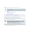
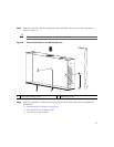
Step 3 Place the switch on the table or shelf near an AC power source.
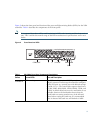
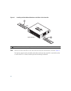
Note Allow 3 inches of space around the controller ventilation openings to prevent airflow
restriction and overheating.
Step 4 After the controller is mounted on a shelf or desk, perform the following tasks to complete
the installation:
• Connecting the Controller Console Port
• Securing the Power Adapter Cable
• Connecting to the Network
Step 5 For configuration instructions about using the CLI setup program, see the “Running the
Bootup Script and Power-On Self Test” section on page 23.
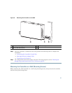
Mounting the Controller on a Wall (Rack-Mount Brackets)
The controller can be mounted on a wall using an optional rack-mount bracket kit that is not included
with the controller. You can order a kit with 19-inch rack mounting brackets and hardware from
Cisco. The kit part number is AIR-CT2504-RMNT.
Warning
Read the wall-mounting carefully before beginning installation. Failure to use the
correct hardware or to follow the correct procedures could result in a hazardous
situation to people and damage to the system.
Statement 378
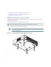
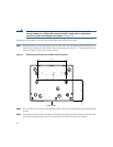
To mount the controller on a wall using rack-mount brackets, follow these steps:
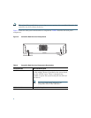
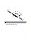
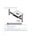
Step 1 Attach the 19-inch brackets to each side of the 2504 controller as shown in Figure 5 with
#10-32 flat head screws provided in the kit.