


16
Warning
Read the wall-mounting carefully before beginning installation. Failure to use the
correct hardware or to follow the correct procedures could result in a hazardous
situation to people and damage to the system.
Statement 378
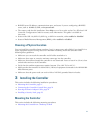
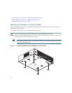
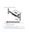
To mount the controller on a wall using mounting screws, follow these steps:
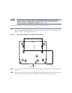
Step 1 Mark the location of the mounting screws on the wall. Use the mount hole locations on the
back of the controller for placement of the mounting screws (
Figure 7). (The mount holes are
shown in Figure 7 with a cross-hatch mark.)
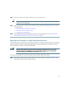
Figure 7 Mounting Screw Holes on the Back of the Controller
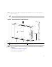
Step 2 Use a 0.107-inch (2.7mm) or #32 drill bit to drill a 3/4 inch (19mm) hole for the two mounting
screws.
Step 3 Insert two screws into the screw holes and tighten until the top of the screws are 1/8 inch from
the wall (leaving enough room for the back panel to slide onto the screws firmly).
282087
3.9
5.5
FRONT PANEL