


23
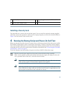
Installing a Security Lock
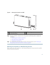
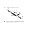
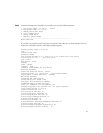
The controller has a security slot on the back panel. You can install an optional customer-supplied
cable lock, such as the type that is used to secure a laptop computer, to secure the controller. Refer to
Figure 3 for the location of the security lock.
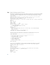
4 Running the Bootup Script and Power-On Self Test
When you plug the controller into an AC power source, the bootup script initializes the system, verifies
the hardware configuration, loads its microcode into memory, verifies its operating system software
load, and initializes itself with its stored configurations. Before performing this test, you should have
connected your PC to the CLI console on the controller as described in the
“Connecting the Controller
Console Port” section on page 21.
To run the bootup script and conduct the power-on self test (POST), follow these steps:
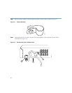
Step 1 Plug the external power supply into the power jack on the back of the controller.
Step 2 Plug a country-specific power cord into the external power supply, then plug the other end
into a grounded 100 to 240 VAC, 50–60 Hz electrical outlet.
Note If you wish to run a previous release of the controller code, press Esc when the boot
loader prompt appears. The Bootloader Options menu appears.
Note When the controller receives power, the green front panel Power LED lights. If the
Power LED does not light, make sure that the electrical outlet is supplying power and
that the power connections to the controller are correct.
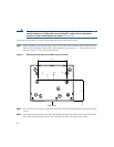
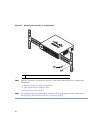
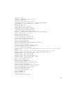
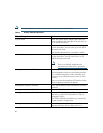
1
Security clip secured with screw
3
Power plugged into the POWER 48VDC
port.
2
AC/DC power adapter cable