


20
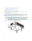
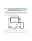
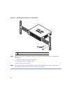
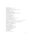
Figure 10 Mounting the Controller in a 19-Inch Rack
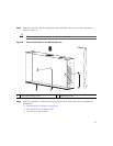
Step 3 After the controller is mounted in the rack, perform the following tasks to complete the
installation:
• Connecting the Controller Console Port
• Securing the Power Adapter Cable
• Connecting to the Network
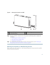
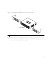
Step 4 For configuration instructions about using the CLI setup program, see the “Running the
Bootup Script and Power-On Self Test” section on page 23.
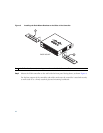
1
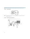
#10-32 pan-head screws or #12-24 slotted head screws
1
2
82086