


17
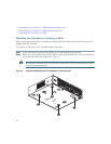
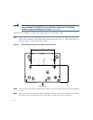
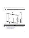
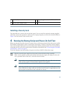
Step 4 Place the controller onto the mounting screws and slide it down until it lock into place, as
shown in
Figure 8.
Note The front panel of the controller should be facing down.
Figure 8 Place the Controller on the Mounting Screws
Step 5 After the controller is mounted ion the wall, perform the following tasks to complete the
installation:
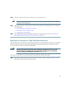
• Connecting the Controller Console Port
• Securing the Power Adapter Cable
• Connecting to the Network
1
Front panel (facing down)
2
Mounting screws
282085
2
1
2