


5
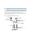
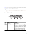
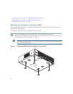
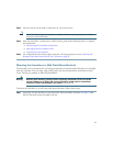
Figure 2 shows the front panel and location of the ports and light-emitting diodes (LEDs) for the 2504
controller. Table 1 describes the components of the front panel.
Note It is expected that there will be small variations in LED color intensity and hue from unit to
unit. This is within the normal range of the LED manufacturer’s specifications and is not a
defect.
Figure 2 Front Panel and LEDs
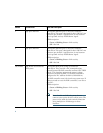
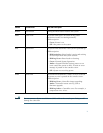
Table 1 WLC2504 Front Panel Component Descriptions
Callout Port and LEDs State and Description
CONSOLE
CPU console port The CPU console port is an RS-232 port that supports
a RJ-45 connector. At boot-up the controller configures
the RS-232 port as a console port with default settings
of 9600, N, 8, 1. The boot-loader supports baud rates
of 1200, 2400, 4800, 9600, 19200, 38400, 57600, and
115200. A default baud-rate recovery mechanism is not
available; however the bootloader ensures that the
stored baud rate setting matches one of the allowed
values before setting the baud rate. If a nonstandard
value is detected the baud rate will default to 9600.
282249
CISCO 2500 Series WIRELESS CONTROLLER
Model 2504
RESET
PWR SYS ALM
CONSOLE
1234
1CONSOLE 2 3-4 POE
PWR ALM
SYS
RESET