Appendix B: Cable List
19
Cisco BTS 10200 Softswitch Cabling and IRDP Procedures - AXmp Option
OL-4883-02
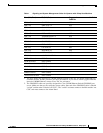
PDU-A-2 CA-B DC-A #52
PDU-A-4 EMS-A DC-A #54
PDU-A-5 CA-A DC-A #55
PDU-A-6 HUB-B DC-A #56
PDU-A-7 HUB-A DC-A #57
PDU-A-8 ALARM PANEL-A #58
PDU-B-1 EMS-B DC-B #61
PDU-B-2 CA-B DC-B #62
PDU-B-4 EMS-A DC-B #64
PDU-B-5 CA-A DC-B #65
PDU-B-6 HUB-B DC-B #66
PDU-B-7 HUB-A DC-B #67
PDU-B-8 ALARM PANEL-B #68
HUB-A Ground PDU Ground
HUB-B Ground PDU Ground
CA-A Ground PDU Ground
CA-B Ground PDU Ground
EMS-A Ground PDU Ground
EMS-B Ground PDU Ground
Alarm Panel Ground PDU Ground
1. The ports shown are applicable to 100 Mb Ethernet uplinks. Cable No. for uplink connections are
customer-defined. See the procedure for more information. If you need to connect gigabit Ethernet
instead of 100Mb Ethernet, contact Cisco TAC for assistance.
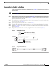
2. The CONSOLE cables are specially designed for Cisco 2924M Ethernet Switch CONSOLE port
access. Make sure that you are using the correct cables. One end of the CONSOLE cable is labeled
“switch” and the other is labeled “net CCN”. The “switch” end must connect to the Hub and the “net
CCN” end must connect to the Alarm Panel.
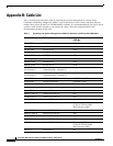
Table 1 Signaling and System Management Cables for Systems with AXmp Host Machines
From (Unit, Port) To (Unit, Port) Suggested
Cable No.
Verified


