


Labeling the Cables
5
Cisco BTS 10200 Softswitch Cabling and IRDP Procedures - AXmp Option
OL-4883-02
• Uplinks for external access to hosts, used for management services (via SSH, SFTP, and so
forth) and outbound billing data (via FTP)
• Uplinks for external communications, used for connection to external NEs and DNS services
via IRDP-enabled network
Note NE = Network element
SSH = Secure shell
SFTP = Secure file transfer protocol (FTP)
DNS = Domain name server
IRDP = Internet control message protocol (ICMP) router discovery protocol
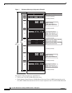
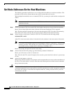
4. To support full system redundancy, it is necessary to connect the two external uplinks to separate
routers as shown in Figure 2. Furthermore, the routers must be connected to separate networks with
diverse routing paths to the applicable external NEs and services (such as OSS, DNS, media
gateways, and announcement servers).
Caution If each of the external uplinks is not connected as described in Note #3, a single point of failure could
cause a traffic interruption.
5. To ensure redundancy of the DNS lookup function in the event of a network outage, it is strongly
recommended to have two DNS servers reachable via separate networks with diverse routing paths.
Caution If both DNS servers become unreachable, a traffic interruption will occur.
Labeling the Cables
Make sure that you have all the cables labeled before you begin. Label the cables according to the
procedure in Appendix A: Cable Labeling, page 17.
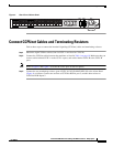
Connect Ethernet Cables To EMS and CA Units
Follow these steps to connect the Ethernet cables. Refer to Figure 1 on page 2 to identify the specific
units in the rack.
Step 1 Obtain the 4 Ethernet cables needed for connections between the rear panel of the Element
Management Systems (EMS A and EMS B) and the two Cisco 2924M Ethernet Switches (Hub A and
Hub B). These cables are listed in Table 1 in Appendix B: Cable List, page 18.
Step 2 Connect the 4 Ethernet cables to the ports on the rear panel of the EMS units as listed in Table 1 in
Appendix B: Cable List, page 18.
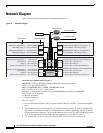
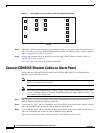
Figure 3 shows the rear view of the AXmp host machine.
Note Figure 3 is not to scale.