


Connect CCPUnet Cables and Terminating Resistors
7
Cisco BTS 10200 Softswitch Cabling and IRDP Procedures - AXmp Option
OL-4883-02
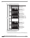
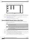
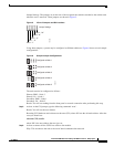
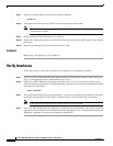
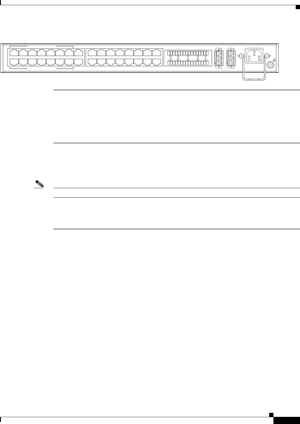
Figure 4 Rear View of Alarm Panel
Connect CCPUnet Cables and Terminating Resistors
Follow these steps to connect the intershelf signaling (CCPUnet) cables and terminating resistors:
Step 1 Obtain the eight CCPUnet cables (four for CCPU A and four for CCPU B).
Step 2 Connect the CCPUnet cables between the machines as listed in Table 1 on page 18. Make sure that you
connect cables labeled CCPU A to the CCPU A ports, and cables labeled CCPU B to the CCPU B
ports.
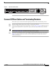
Note Refer to Figure 3 and Figure 4 to locate the CCPU ports on the rear panels.
Step 3 Connect the two terminating resistors (part # CCPU 012 02150-02602 REV 00) to the Alarm Panel
(Figure 4) as follows: Connect one resistor to CCPUNet HUB A port 5, and the other resistor to
CCPUNet HUB B port 5.
CCPUNet HUB A
CCPUNet HUB B
LINE
REM
SER 1
SER 2
SER 3
SER 4
SER 5
SER 6
SER 7
SER 8
SER 9
SER 10
SER 11
SER 12
CONS
COM1
eth1
eth0
I/O CABLE A
I/O CABLE B
-48V A -48V B
100-240 V-
50-60 HZ 40W
AC IN
69752
12345678
12345678