


3-3
Cisco UCS C200 Server Installation and Service Guide
OL-20732-02
Chapter 3 Maintaining the Server
Status LEDs
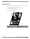
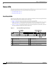
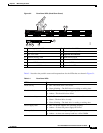
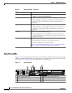
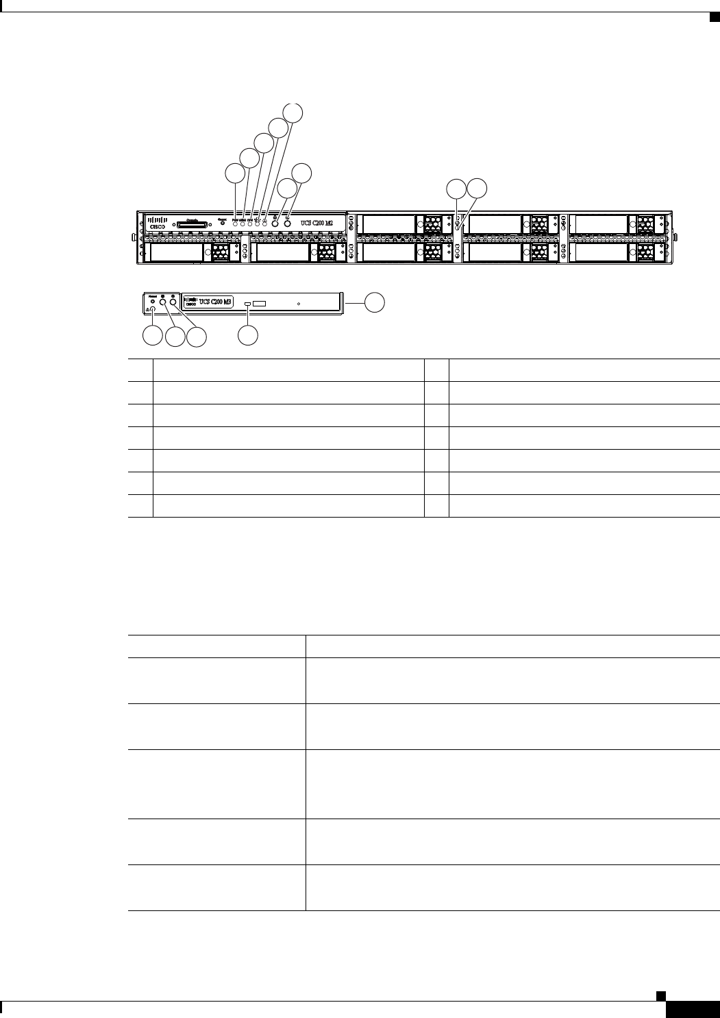
Figure 3-2 Front Panel LEDs (Small Form Factor)
Table 3-1 describes the possible states and interpretations for the LEDs that are shown in Figure 3-1.
1 Power supply fault LED 8 Hard drive fault LED
2 Memory fault LEDs 9 Hard drive activity LED
3 CPU fault LED 10 Optional DVD module
4 Network activity LED 11 DVD activity LED
5 System fault LED 12 Power status LED/Power button
6 Locator LED/Locator button 13 Locator LED/Locator button
7 Power status LED/Power button 14 System fault LED
-A-
8
1
2
3
4
5
6 9
7
14 11
10
13
12
239131
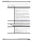
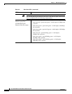
Table 3-1 Front Panel LEDs
LED Name State
DVD activity
• Off—The DVD drive is not in use.
• Green, blinking—The DVD drive is reading or writing data.
Hard drive fault
• Off—The hard drive is operating properly.
• Amber—This hard drive has failed.
Hard drive activity
• Off—There is no hard drive in the hard drive sled.
• Green—The hard drive is ready.
• Green, blinking—The hard drive is reading or writing data.
Power supply fault
• Off—All power supplies are operating properly.
• Amber—At least one power supply has failed.
Memory fault
• Off—All DIMMs are operating properly.
• Amber—At least one memory bank has a failed DIMM.