


3-11
Cisco UCS C200 Server Installation and Service Guide
OL-20732-02
Chapter 3 Maintaining the Server
Preparing for Component Installation
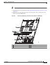
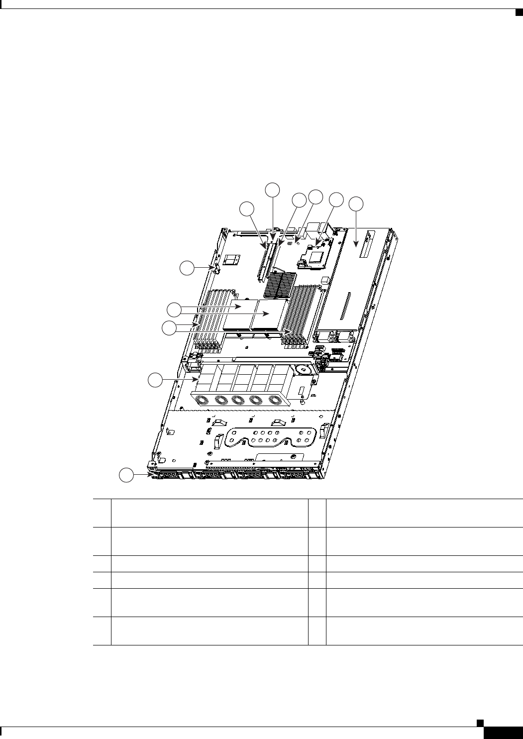
Replaceable Component Locations
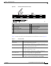
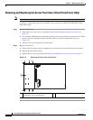
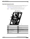
This section shows the locations of the components that are discussed in this chapter. The view shown
is from the top down, with the top cover, internal cable cover, and internal air baffles removed.
• Figure 3-6 shows the Large Form Factor (LFF) version of the server.
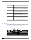
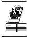
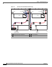
• Figure 3-7 on page 3-12 shows the Small Form Factor (SFF) version of the server.
Figure 3-6 Replaceable Component Locations, Large Form Factor (Top View)
1 Hard drives (up to four, accessible through
front bays)
7 Riser card assembly
2 Fan tray 8 PCIe card connector on riser card (with
low-profile slot)
3 DIMM slots (up to 12) 9 Socket for trusted platform module (TPM)
4 CPUs and heatsinks (up to two) 10 Socket for mezzanine card
5 Motherboard CMOS battery 11 Power supplies (up to two, accessible through
rear bays)
6 PCIe card connector on riser card (with
standard-profile slot)
6
7
8
11
9
10
1
2
5
3
4
195724