


3-4
Cisco UCS C200 Server Installation and Service Guide
OL-20732-02
Chapter 3 Maintaining the Server
Status LEDs
Rear Panel LEDs
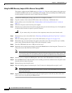
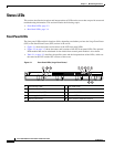
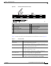
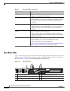
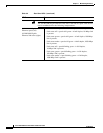
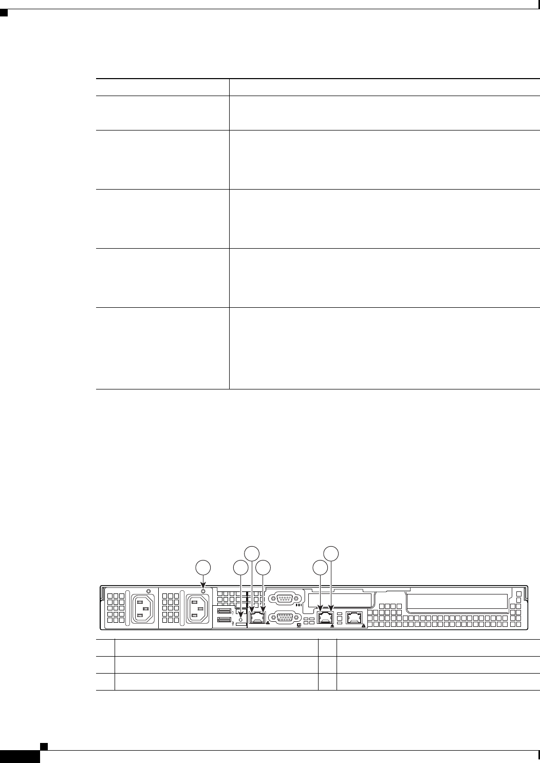
Figure 3-3 shows the names and locations of the rear panel LEDs. A Generation M2 server is shown (the
USB ports and the 10/100 Ethernet management port are in slightly different positions for Generation
M1). See Table 3-2 on page 3-5 for the interpretations of the LED states.
Figure 3-3 Rear Panel LEDs
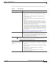
CPU fault • Off—All CPUs are operating properly.
• Amber—At least one CPU has failed.
Network activity
• Off—The server is powered off or in standby power mode.
• Green, blinking—The server is communicating with the network in
main power mode. The blink rate is faster as network activity
increases.
System fault
• Green—The server is operating properly.
• Amber, blinking—An event that requires a service action has been
detected. Investigate other LEDs and check logs to isolate the
problem.
Locator
• Off—The Locator LED is not in use.
• Blue, flashing—The Locator LED/button was pressed and the
Locator LED flashes on the front and rear panels to help you find
the server in a rack.
Power status
• Off—No AC power is present.
• Green, blinking—The server is in standby power mode.
• Green—The server is in main power mode.
See the “Connecting and Powering On the Server (Standalone Mode)”
section on page 2-9 for definitions of these power modes.
Table 3-1 Front Panel LEDs (continued)
LED Name State
1 Power supply status LED 4 10/100 Ethernet link status LED
2 Rear Locator LED 5 10/100/1000 Gigabit Ethernet speed LED
3 10/100 Ethernet speed LED 6 10/100/1000 Gigabit Ethernet link status LED
M
1/M
2
1 42 5
3 6
195750