


3-12
Cisco UCS C200 Server Installation and Service Guide
OL-20732-02
Chapter 3 Maintaining the Server
Preparing for Component Installation
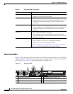
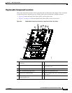
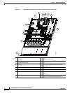
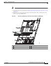
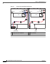
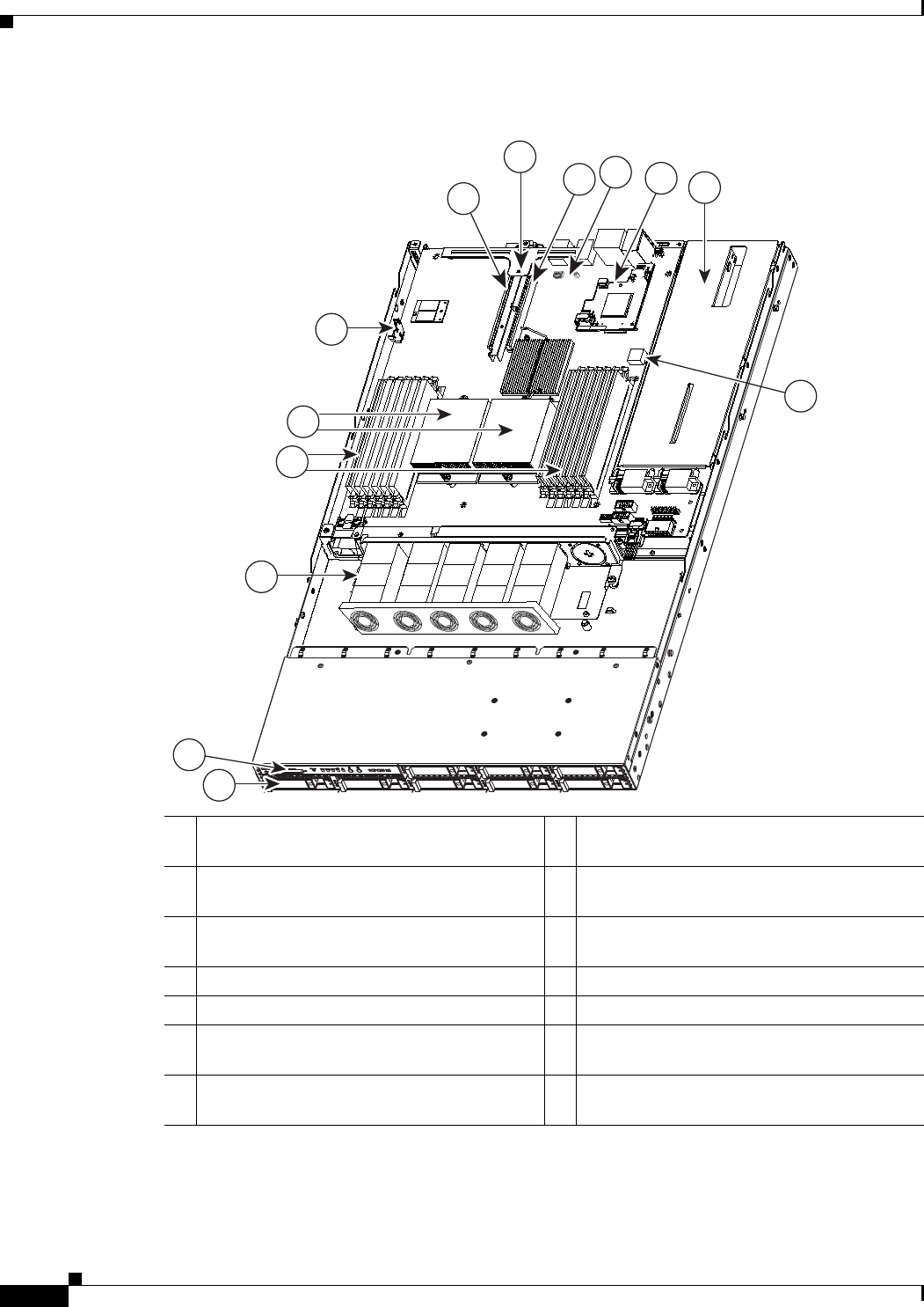
Figure 3-7 Replaceable Component Locations, Small Form Factor (Top View)
1 Hard drives (up to eight, accessible through
front bays)
7 PCIe card connector on riser card (with
standard-profile slot)
2 Front panel control module or
optional DVD module
8 Riser card assembly
3 Fan tray 9 PCIe card connector on riser card (with
low-profile slot)
4 DIMM slots (up to 12) 10 Socket for trusted platform module (TPM)
5 CPUs and heatsinks (up to two) 11 Socket for mezzanine card
6 Motherboard CMOS battery 12 Power supplies (up to two, accessible through
rear bays)
13 Internal USB port on motherboard
(active in server Generation M2 only)
7
8
12
13
3
6
4
5
310370
1
2
9
10
11