


1-3
Cisco ME 3400 Ethernet Access Switch Hardware Installation Guide
OL-7677-04
Chapter 1 Product Overview
Front Panel Description
Cisco ME 3400-24TS AC and DC Switches Front Panel
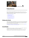
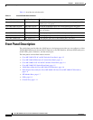
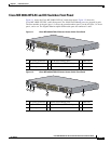
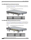
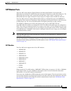
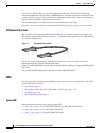
Figure 1-1 shows the Cisco ME 3400G-24TS AC switch front panel. Figure 1-2 shows the
Cisco ME 3400G-24TS DC switch front panel. The 10/100 Fast Ethernet ports are grouped in pairs.
The first member of the pair (port 1) is above the second member (port 2) on the left. Port 3 is above
port 4, and so on. The Gigabit Ethernet uplink SFP module ports are numbered 1 and 2.
Figure 1-1 Cisco ME 3400-24TS AC Ethernet Access Switch Front Panel
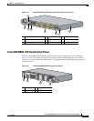
Figure 1-2 Cisco ME 3400-24TS DC Ethernet Access Switch Front Panel
1 AC power connector 4 10/100 Fast Ethernet ports 7 Cable lock
2 System LED 5 Gigabit Ethernet SFP module ports
3 Console port 6 Ground connector
C
isco M
E
3
4
00
SE
R
IES
CONSOLE
1
2
3
4
5
6
7
8
9
1
0
1
1
1
2
1
X
2
X
1
1
X
1
2
X
1
4
1
5
1
6
1
7
1
8
1
9
2
0
2
1
2
2
2
3
2
4
1
3
13
X
14
X
2
3X
24X
1
2
S
Y
S
T
E
M
R
AT
IN
G
100
-240
V
~
1
A
-0
.5
A
, 50
-60
H
Z
191300
3
4
1
5
6
7
2
1 DC power connector 4 10/100 Fast Ethernet ports 7 Cable lock
2 System LED 5 Gigabit Ethernet SFP module ports
3 Console port 6 Ground connector
C
isco
M
E
3
4
0
0
SER
IES
IN
P
U
T
-
3
6
–
-
7
2
V
C
U
R
R
E
N
T
2
–
1
A
A
B
+
+
CONSOLE
1
2
3
4
5
6
7
8
9
1
0
1
1
1
2
1
X
2
X
1
1
X
1
2
X
1
4
1
5
1
6
1
7
1
8
1
9
2
0
2
1
2
2
2
3
2
4
1
3
13X
14X
23X
24X
S
Y
S
T
E
M
1
2
191301
3
4
1
5
7
6
2