


C-9
Cisco ME 3400 Ethernet Access Switch Hardware Installation Guide
OL-7677-04
Appendix C Connecting to DC Power
Wiring the DC-Input Power Source
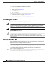
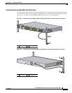
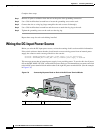
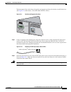
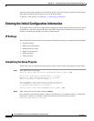
The front panel of the switch shows the positive and negative positions for both the A and B feed wires
(See Figure C-9, which shows a Cisco ME 3400-24TS-DC switch.)
Figure C-9 Positive and Negative Positions
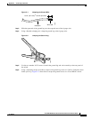
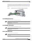
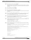
Step 4
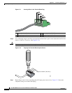
Using an 18-gauge wire-stripping tool, strip each of the four wires coming from the DC-input power
source to 0.27 inch (6.6 mm) ± 0.02 inch (0.5 mm). Do not strip more than 0.29 inch (7.4 mm) of
insulation from the wire. Stripping more than the recommended amount of wire can leave exposed wire
from the terminal block plug after installation.
Figure C-10 Stripping the DC-Input Power Source Wire
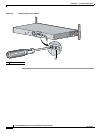
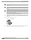
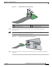
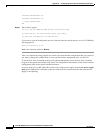
Step 5
Insert the exposed wire of one of the four DC-input power source wires into the terminal block plug, as
shown in Figure C-11. Make sure that you cannot see any wire lead. Only wire with insulation should
extend from the terminal block.
Warning
A readily accessible two-poled disconnect device must be incorporated in the fixed wiring.
Statement 1022
CONSOLE
132858
SYSTEM
INPUT -36 – -72 V
CURRENT 2 – 1A
A
B
+
+
SYSTEM
0.25 in. (6.3 mm)
±
0.02 in. (0.5 mm)
60531